Table of Contents
Advertisement
Available languages
Available languages
Quick Links
Bedienungsanleitung
DE
EN
Multi-GMAW 200S
MIG/MAG, MMA, WIG Schweißinverter / MIG/MAG, MMA, TIG
IMPORTANT: Read this Owner's Manual Completely before attempting to use this
equipment. Save this manual and keep it handy for quick reference. Pay particular
attention to the safety instructions we have provided for your protection. Contact your
distributor if you do not fully understand this manual.
User Manual
Welding Inverter
1.0003.0520-E
V 2.0.22
Advertisement
Chapters
Table of Contents
Troubleshooting

Related Manuals for MK Welding Multi-GMAW 200S


Summary of Contents for MK Welding Multi-GMAW 200S
- Page 1 Bedienungsanleitung User Manual Multi-GMAW 200S MIG/MAG, MMA, WIG Schweißinverter / MIG/MAG, MMA, TIG Welding Inverter 1.0003.0520-E V 2.0.22 IMPORTANT: Read this Owner’s Manual Completely before attempting to use this equipment. Save this manual and keep it handy for quick reference. Pay particular attention to the safety instructions we have provided for your protection.
-
Page 2: Table Of Contents
Inhaltsverzeichnis Sicherheitsanweisung Betriebsbedingungen und Arbeitsumgebung Technische Beschreibung Technische Daten Einschaltdauer Funktionsbezeichnung Kontrollpaneel MIG/MAG Schweißen MMA Schweißen WIG Schweißen Fehlerursachen - Behebung Prüfen und Warten Schematischer Schaltplan Copyright © 2020 MK Trade GmbH, Wies, Österreich. Die Inhalte dieser Bedienungsanleitung sind alleiniges Eigentum der Firma MK Trade GmbH. Eine Weitergabe sowie Vervielfältigung dieses Dokuments, Verwertung und Mitteilung seines Inhalts sind verboten, soweit nicht ausdrücklich gestattet. -
Page 3: Sicherheitsanweisung
1. Sicherheitsanweisung Die Anlage ist ausschließlich für das MIG/MAG/MMA/TIG Schweißen bestimmt. Das Bedienungspersonal muss über die Sicherheitshinweise unterrichtet werden. Die Anlage darf unter keinen Umständen von ungeschultem Personal bedient werden. Reparaturen im elektrischen Bereich dürfen nur von Elektrofachkräften ausgeführt werden. Bei Pflege-, Wartungs- und Reparaturarbeiten sowie vor Öffnen des Gehäuses immer Netzstecker ziehen. - Page 4 Alle an der Anlage angeschlossenen elektrischen Leitungen sind auf einwandfreien Zustand zu überprüfen. Warnung: Blanke Stellen ohne bzw. mit schadhafter Isolierung sind lebensgefährlich. Beschädigte Kabel bzw. Schlauchpakete sofort ersetzen! Beim Wechsel der Brennerteile die Anlage am Hauptschalter außer Betrieb setzen. Vor öffnen des Anlagengehäuses durch ein Fachpersonal, Netzstecker ziehen.
- Page 5 Personen, die Herzschrittmacher oder Hörgeräte tragen, sollten sich vor Arbeiten in der Nähe der Maschinen, von einem Arzt beraten lassen. Achtung: Es ist möglich, dass im Bereich eines Krankenhauses oder ähnlichem durch den Betrieb der Anlage elektromedizinische, informationstechnische oder auch andere Geräte (EKG, PC, usw.) in ihrer Funktion beeinträchtigt werden können.
-
Page 6: Betriebsbedingungen Und Arbeitsumgebung
Normen (EMC 2014/30/EU & LVD 2014/35/EU, EN 60974-10:2014 + A1:2015, EN60974- 1:2012). Das Multi-GMAW 200S Schweißgerät besitzt die modernste IGBT Technologien. Es hat mehr Leistung und höhere Effektivität so dass es mit üblichen Transformator Schweißgeräten nicht vergleichbar ist. Der Schweißstrom ist sehr stabil. Das Schweißgerät hat hervorragende Eigenschaften bei Minimum - Strom. -
Page 7: Einschaltdauer
5. Einschaltdauer Multi-GMAW 200S SYN Der Buchstabe „X“ steht für 200A Einschaltdauer (Duty Cycle). Hierbei handelt es sich um den Teil der Zeit, in 180A der ein Schweißgerät innerhalb eines bestimmten Zeitzyklus (10 Minuten) kontinuierlich mit seinem 160A Ausgangsnennstrom schweißen kann. -
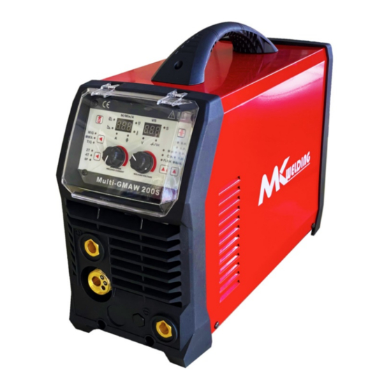
Page 8: Funktionsbezeichnung
6. Funktionsbezeichnung Bild 1 1. Euro Zentral Anschluss 2. Ausgang MINUS (-) 3. Ausgang PLUS (+) 4. Ein / Aus Schalter 5. Gas Eingang 6. Kabel 7. Drahtrollen Halter... - Page 9 8. Spannschraube, Drahtanpressdruck 9. Druckrolle 10. Drahtführungs Rohr 11. Draht Vorschubrolle 12. Vorschubmotor 13. PLUS POL „+“ 14. MINUS POL „-„ Je nach verwendetem Schweißdraht (siehe Hersteller Angaben, Schweißdraht) muss die Polung des Eurozentral Anschusses umgepolt werden, hierzu ist das Kabel auf dem Anschluss (Bild 1, 13) Plus Pol oder auf (Bild 1, 14) Minus Pol anzuschließen, das Massekabel muss je nach Polung des Euro Zentral Anschlusses auf den anderen Pol angeschlossen werden.
-
Page 10: Kontrollpaneel
7. Kontrollpaneel Bild 2 1 Gastest 2 Auswahltaster Schweißverfahren MIG/MAG, WIG (Kontakt Zündung), MMA 3 Auswahl 2 Takt / 4 Takt / Spot 4 Drehregler, Schweißstrom, Drahtvorschubgeschwindigkeit, Hot Start, Arc Force 5 Drehregler, Schweißspannung, Induktion (ind), Drahtrückbrand (bub), Spot Zeit (SPt) 6 Auswahl Synergic Programm / Manuell 7 Drahtvorschub 8 Display, Spannungsanzeige (V), Induktion, Drahtrückbrand, Spot Zeit (sek.) -
Page 11: Mig/Mag Schweißen
8. MIG/MAG Schweißen Das Gerät muss auf den MIG / MAG Modus umgestellt werden, hierzu muss der Tastknopf (Bild 2, 2) gedrückt werden bis die MIG LED aufleuchtet (LED ganz oben). Mit dem Tastknöpfen (Bild 2, 6) kann das gewünschte Synergic Programm (Gas und Drahtstärke) bzw. Manuell (MAN.) ausgewählt werden. -
Page 12: Wig Schweißen
10. WIG Schweißen (Kontakt Zündung) Das Gerät muss auf den WIG Modus umgeschaltet werden, hierzu muss der Tastknopf (Bild 2, 2) gedrückt werden bis die LED „TIG“ aufleuchtet (LED ganz unten). Das WIG Schlauchpaket gehört auf den MINUS POL (Bild 1, 2) und das Massekabel auf dem PLUS POL (Bild 1, 3). -
Page 13: Fehlerursachen - Behebung
11. Fehlerursachen - Behebung Fehler Mögliche Ursache Behebung Netz angeschlossen und Netzsicherung hat ausgelöst Netzsicherung prüfen Netzschalter auf „I“ – Netzanschluss unterbrochen Netzanschluss prüfen Kontrollleuchte Netz leuchtet nicht Alarmleuchte leuchtet Gerät ist Überhitzt Der Alarm wird nach Ablauf der Lüfterkühlung freigegeben und Sie können das Gerät neu starten Überstrom Die Alarmleuchte leuchtet... -
Page 14: Prüfen Und Warten
12. Prüfen und Warten Intervall Zu Prüfen Täglich - Das Netzkabel, Verbindungskabel auf Beschädigungen Prüfen. (bei defekt autorisiertes Fachpersonal kontaktieren). - Massekabel, Schlauchpaket, Elektrodenhalter auf Beschädigungen Prüfen und bei Bedarf wechseln. - Gerät auf äußere Beschädigungen Prüfen. - Ein/ Ausschalter auf Beschädigung Prüfen. (bei defekt autorisiertes Fachpersonal kontaktieren). -
Page 15: Schematischer Schaltplan
13. Schematischer Schaltplan... - Page 16 CONTENT §1 Safety ......................1 §1.1 Signal Explanation ................... 1 §1.2 Arc Welding Damage ................1 §1.3 The knowledge of Electric and Magnetic Fields .......... 6 §2 Overview ..................... 7 §2.1 Brief Introduction ..................7 §2.2 Working Principle ..................7 §2.3 Volt-Ampere Characteristic ...............
-
Page 17: Safety
SAFETY §1 Safety §1.1 Signal Explanation — The above signals mean warning! Notice! Running parts and getting an electric shock or thermal parts will take damage for your body or others. The corresponding notices are as follows. It is quite a safe operation after taking several necessary protection measures. - Page 18 SAFETY — Never close the machine power before installation and adjustment. Ensure to install the equipment correctly and ground the work or metal to be welded to a good electrical (earth) ground according the operation manual. —The electrode and work (or ground) circuits are electrically “hot” when the welder is on.
- Page 19 SAFETY mechanical ventilation. In confined spaces or in some circumstances, outdoors, a respirator may be required. Additional precautions are also required when welding on galvanized steel. — Do not weld in locations near chlorinated hydrocarbon vapors coming from degreasing, cleaning or spraying operations. The heat and rays of the arc can react with solvent vapors to form phosgene, a highly toxic gas, and other irritating products.
- Page 20 SAFETY governor or idler by pushing on the throttle control rods while the engine is running. DO NOT adds the fuel near an open flame welding arc or when the engine is running. Stop the engine and allow it to cool before refueling to prevent spilled fuel from vaporizing on contact with hot engine parts and igniting.
- Page 21 SAFETY garments such as leather gloves, heavy shirt, cuff less trousers, high shoes and a cap over your hair. Wear ear plugs when welding out of position or in confined places. Always wear safety glasses with side shields when in a welding area. —...
-
Page 22: The Knowledge Of Electric And Magnetic Fields
SAFETY §1.3 The knowledge of Electric and Magnetic Fields Electric current flowing through any conductor causes localized Electric and Magnetic Fields (EMF). The discussion on the effect of EMF is ongoing all the world. Up to now, no material evidences show that EMF may have effects on health. -
Page 23: Overview
OVERVIEW §2 Overview §2.1 Brief Introduction MIG SERIES arc welding machine adopts the latest pulse width modulation (PWM) technology and insulated gate bipolar transistor (IGBT) power module, which can change work frequency to medium frequency so as to replace the traditional hulking work frequency transformer with the cabinet medium frequency transformer. -
Page 24: Volt-Ampere Characteristic
OVERVIEW medium transformer (the main transformer) and rectifying by medium frequency rectifier (fast recovery diodes), and is outputted by inductance filtering. when MIG. Meanwhile, the welding current parameter can be adjusted continuously and infinitely to meet with the requirements of welding craft. single-phase 220V 50/60HZ §2.3 Volt-Ampere Characteristic... -
Page 25: Principles Of Welding
OVERVIEW §2.4 Principles of welding Nur Hauptdokument... -
Page 26: Installation And Adjustment
INSTALLATION AND ADJUSTMENT §3 Installation and Adjustment §3.1 Parameters Model MULTI-GMAW 200S Parameters Input Voltage (V) 1~220/230/240±10% Input Current (A) 40 MIG 38.6 MMA 28 TIG Input Power (KW) 5.6 MIG 5.8 MMA Welding Current (A) 40-200 MIG 10-180 MMA... -
Page 27: Duty Cycle And Over-Heat
INSTALLATION AND ADJUSTMENT §3.2 Duty cycle and Over-heat The letter “X” stands for the duty cycle, which is defined as the proportion of the time that a machine can work continuously within a certain time (10 minutes). The rated duty cycle means the proportion of the time that a machine can work continuously within 10 minutes when it outputs the rated welding current. -
Page 28: Maintenance Of Mig Gun Mechanism
INSTALLATION AND ADJUSTMENT 6、Connect the control cable pin of torch with the two-lead aero socket of front panel on welding machine. 7、Notice that the wire diameter should be accordant with the wire wheel and torch tip and press the wire properly with the hand §3.4 Maintenance of MIG Gun mechanism §3.4.1 Dissection graphics for the MIG GUN §3.4.2 The parts list for the MIG GUN... -
Page 29: Maintenance Of The Wire Feed Mechanism
OPERATION 1. Service the wire feed mechanism at least every time the reel is changed. ·Check the wear of the feed roll groove and change the feed roll when necessary. ·Clean the welding gun wire guide with compressed air. 2. Cleaning the wire guide Pressure of the feed rolls remove metal dust from the filler wire’s surface which then finds its way to the wire guide. - Page 30 OPERATION Attach the reel with a reel lock. Unfasten the wire end from the reel, but hold on it all the time. Straighten the wire end for approximately 20 cm and cut the wire in the straightened location. Open the pressure control level which then opens the feed gear. Thread the wire through the wire’s rear guide to the gun’s wire guide.
-
Page 31: Layout For The Front And Rear Panel
OPERATION §4 Operation §4.1 Layout for the front and rear panel 1. MIG GUN Connect. 2.Output cathode: When MIG mode, this polarity must connect the work piece. 3.Output anode: When MMA mode, this polarity connect welding clamp or the work piece 4.On/off switch: Control the power supply on and off. -
Page 32: Welding Operation
OPERATION §4.2 Welding operation For example 1. Air Check Select 2. Choose welding method key: Pressing the key can choose three kinds material, MIG/MMA/LIFT TIG 3. 2T/4T /S4T/Spot Weld Select 4. Welding current/ARC FORCE/ HOT START knob: Set the welding current、ARC FORCE、HOT START. -
Page 33: Mig Mode Operation
OPERATION §4.2.1 MIG mode operation: 1. Shielding Gas choice 1) When the wire material is Fe, the shielding gas is 80%Ar + 20%CO2 ; 2) When the wire material is Ss, the shielding gas is 98%Ar + 2%O2 ; 3) When the wire material is Al, the shielding gas is 100%Ar. 2. -
Page 34: Welding Parameters
OPERATION §4.3 Welding parameters Wire speed Welding current Welding volt Wave φ φ φ (A) (V) control 2--3 13~15V 3--5 2--3 14~16V 6--8 3--5 2--3 15~17V 100A 3--6 16~19V 120A 17~20V 4--7 3--5 140A 19~21V 5-10 5--8 3--5 160A 20~22V 5-10 6--9 4--7... -
Page 35: Maintenance & Troubleshooting
OPERATION ▲ Ensure good ventilation of the machine to improve duty ratio. ▲ Turn off the engine when the operation finished for economize energy sources. ▲When power switch shuts off protectively because of failure. Don’t restart it until problem is resolved. Otherwise, the range of problem will be extended. ▲In case of problems, contact your local dealer if no our authorized maintenance man. -
Page 36: Troubleshooting
THANK YOU FOR USING OUR PRODUCTS fan rotates normally, the start capacity should be replaced; If not, change the fan. Observe that whether the fast connector is loose or overheated. if the arc welding machine has the above problems, it should be fastened or changed. - Page 37 THANK YOU FOR USING OUR PRODUCTS Troubles Reasons Solution Breaker damaged Change it Close the breaker, but the Fuse damaged Change it power light isn’t on Power damaged Change it After welding machine is Fan damaged Change it over-heat, the fan doesn’t work The cable is loosen Screw the cable tightly...
-
Page 38: Electrical Schematic Drawing
THANK YOU FOR USING OUR PRODUCTS §5.3 Electrical schematic drawing Nur Hauptdokument... - Page 39 Produkt Marke: MK Welding Produkt Gruppe: Schweißgerät Produkt Type: MIG/MAG, WIG, MMA Schweißgerät Bezeichnung des Produktes: Multi-GMAW 200S Seriennummer*: 1.0003.0520-E_____________________ Baujahr*: 20_________ (Ersichtlich anhand der Seriennummer) * anhand des Typenschildes am Gerät Auszufüllen Das oben genannte Erzeugnis stimmt mit den Vorschriften folgender Europäischen Richtlinien überein:...
Need help?
Do you have a question about the Multi-GMAW 200S and is the answer not in the manual?
Questions and answers