Advertisement
Quick Links
Advertisement

Related Manuals for ANPVIZ HK Series


Summary of Contents for ANPVIZ HK Series
- Page 1 User Manual HK Series Network Dome Camera EN / DE / FR / ES / IT Version...
- Page 2 Thank you very much for choosing ANPVIZ. Our products are supported by the world's first video monitoring manufacturers. and they have adopted military level of protection. It is our top priority to ensure your data safety and offer you a satisfactory service.
- Page 3 About this Manual The Manual includes instructions for using and managing the product Picture, charts, images and all other information hereinafter are for description and explanation only. The information contained in the Manual is subject to change, without notice, due to firmware updates or other reasons.
- Page 4 —Increase the separation between the equipment and receiver. —Connect the equipment into an outlet on a circuit different from that to which the receiver Is connected. —Consult the dealer or an experienced radio/TV technician for help. FCC Conditions This device complies with part 15 of the FCC Rules. Operation is subject to the following two conditions: 1.
- Page 5 Warnings: Serious Injury or death may occur if any of the warnings are neglected. Cautions: Injury or equipment damage may occur if any of the cautions are neglected. Warnings: Follow these safeguards to Cautions: Follow these precautions to prevent serious injury or death. prevent potential injury or material damage.
- Page 6 • Do not place the camera In extremely hot, cold (the operating temperature shall be -30°C to +60°C, or -40"C to +60*C if the camera model has an "H1 in its suffix), dusty or damp Locations, and do not expose it to high electromagnetic radiation. •...
-
Page 7: Appearance Description
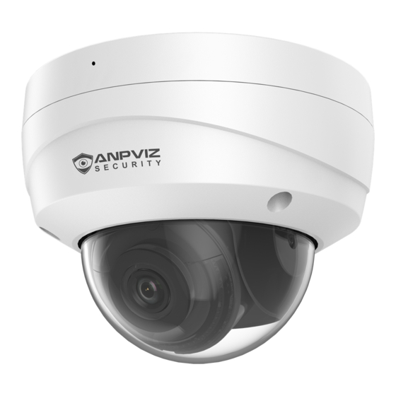
1. Appearance Description Type I: Figure 1-1 Figure 1-1 Camera Overview Table 1-1 Camera Description Description Mounting Base Panning Adjusting Bracket Front Cover Power Cord Network Cable IR LED Lens Black Liner Safety Rope - 6 -... - Page 8 2. Installation Before you start: ● Make sure the device in the package is in good condition and all the assembly parts are included. ● The standard power supply is 12 VDC or PoE. Make sure your power supply matches with your camera. ●...
-
Page 9: Installation
2.1 Installation For camera models that support memory card as local storage, you can follow the steps to mount and unmount the memory card. Steps: 1. Loosen the screws on the bubble. Remove the bubble to expose the memory card slot. Figure 1-1 Remove Bubble Notes: ●... - Page 10 2. Find the memory card slot to insert the memory card. Figure 1-1 Insert Memory Card 3. (Optional) To unmount the memory card, push to get it ejected. 2.2 Ceiling Mounting Step: 1. Paste the drill template to the desired mounting place. 2.
- Page 11 Figure 2-3 Drill Template Notes: ● If you choose to route cable through the ceiling, cut a cable hole according to Hole A on drill template. ● You can also route cable from the side outlet as shown in . ●...
- Page 12 Figure 2-4 Side Outlet 3. Route the cables and fix the mounting base on the ceiling with three screws. 4. Adjust surveillance angle. 1). Loosen one tilting adjusting screw to adjust the tilting position. Tighten the screw after adjustment. 2). Hold the black liner to adjust the panning position. - 11 -...
- Page 13 Figure 2-6 2-Axis Adjustment 5. Install the bubble back to the camera. Figure 2-7 Install Bubble 2.3 Mounting with Brackets This camera series supports mounting with wall mounting bracket and pendant mounting bracket. - 12 -...
- Page 14 2.3.1 Wall Mounting with Junction Box The wall mounting bracket with junction box is not included in the package. You need to prepare one, if you adopt this mounting type. Steps: 1. Mark the screw holes on desired mounting place. 2.
- Page 15 1. Unscrew the bubble of the camera. 2. (Optional) Insert the memory card to the camera, if your camera supports memory card installation. Refer to Section . 3. Fix the camera to the cap of the wall mounting bracket. Figure 2-1 0 Fix the Camera to Wall Mounting Bracket 1.
- Page 16 Figure 2-11 Fix the Pendant Mount 4. Unscrew the bubble of the camera. 5. (Optional) Insert the memory card to the camera, if your camera supports memory card installation. Refer to Section . 6. Fix the camera to the cap of the pendant mounting bracket with three supplied self-tapping screws.
- Page 17 7. Screw the cap to the pendant mounting bracket. Figure 2-1 3 Install the Cap 1. Adjust surveillance angle of camera. Refer to Step 4 in Section 2.2. 2. Install the bubble back to the camera. 2.4 Waterproof Measures If the camera is installed outdoor, you should use the waterproof accessory or tapes to waterproof the cables.
- Page 18 2.4.1 Install Network Cable Waterproof Jacket Figure 2-1 4 Install Waterproof Jacket Step: 1. Feed the network cable through ① and ③ in order. 2. Fix ② on the network cable between ① and ③. 3. Place ⑤ onto the end of ⑥, and plug the RJ45 male connector into RJ45 female connector.
- Page 19 Figure 2-15 Waterproof Cables 3. Activate and Access Network Camera Scan the QR code to get Activate and Access Network Camera. Note that mobile data charges may apply if Wi-Fi is unavailable - 18 -...
- Page 20 4. Operate IP Cameras via IE Browser You can configure the IP cameras In the LAN network via the IE browser. 1. Power on the camera with a DC 12 V adapter and connect it to the same router as your computer with a network cable.
- Page 21 4. Double click the camera's address or you can input the IP address on the IE browser to enter the login page. The default account name is admin and the password is the one you just set up. 5. Download and install the plug-in to view live video and manage the camera. Close the browser when installing the plug-in.
- Page 22 5. Remote Live Stream via Smart phones You can view the IP camera remotely via your mobile phone with the GuardingVision App. 1. Power on the camera with a DC 12 V adapter and connect it to the same router as your computer with a network cable.
- Page 23 4. Click Read and Agree GuardingVision terms of service to enable GuardingVision service before continuing to add the device. Create a verification code and finish the adding process. After that, the device will be shown in the device list. Click the device name to get live view.
- Page 24 3. Launch Guarding Vision/IVMS 4200 software. The control panel and live view interface of Guarding Vision/IVMS 4200 are shown below. 4.Go to Control Panel-Device Management-Device. At the bottom of the screen and in the Online Devices section, the screen will display all devices on the network. Create a password to active the device if the device's status is inactive.
- Page 25 6.Go to Control Panel-Main View. If you have added the IP camera, you can get a live view in the screen (as shown in the picture below). For more information, Please press F1 to get user manual 7. View Live Stream with Other Software thats Supports RTSP Protocol The IP camera supports RTSP protocol.
- Page 26 8. Connect IP Cameras to ANPVIZ NVRs 1. Please confirm that the resolution of the IP camera is not higher than the resolution that the NVR supports. For example, the maximum resolution that the NVR108-8P NVR supports is 8MP. You can only connect the IP camera with up to 8MP resolution.
- Page 27 4. After logging in the camera, please go to Configuration -> Network -> Advance Setting -> Integration Protocol. Check the Enable ONVIF box. Click Add to create an ONVIF account and password. The ONVIF account and password will be used when you add the IP camera to the third-party NVR or DVR.
- Page 28 Anpviz Security Electronics Co.,Ltd. Tech Support Email Address: support@annpvizsecurity.com Made in China...
Need help?
Do you have a question about the HK Series and is the answer not in the manual?
Questions and answers