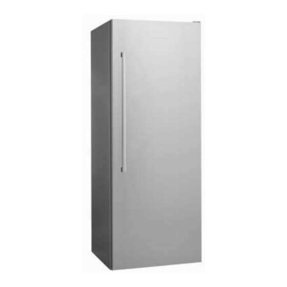
Fisher & Paykel E373 Service Manual
Electronic single temperature refrigerators
Hide thumbs
Also See for E373:
- Installation instructions & user manual (48 pages) ,
- Installation instructions and user manual (44 pages) ,
- Installation instructions and user manual (36 pages)
Table of Contents
Advertisement
Advertisement
Table of Contents

Summary of Contents for Fisher & Paykel E373
- Page 1 Electronic Single Temperature Refrigerators Models E373 & E450 517672...
- Page 2 517672 - JULY 2006 Reprint JANUARY 2007 The specifications and servicing procedures outlined in this manual are subject to change without notice. The latest version is indicated by the reprint date and replaces any earlier editions. MODELS AND PRODUCT CODES 22107 E450LXFD D FP SX 12 25648 RF373SLDW1 FP AA 22309 E450LXFD D FP SX 18...
-
Page 3: Table Of Contents
517672 CONTENTS INTRODUCTION ........................4 Electronics ..........................4 Product Specification ......................4 1.2.1 Compressors ........................4 1.2.2 Compressor Specification ....................4 Condenser Layout ........................4 ELECTRONICS ........................5 Control Module ........................5 Light Operation ........................5 Temperature Controller ......................5 Beeper/Alarm ......................... -
Page 4: Introduction
The operational component such as the evaporator has also changed from the corrugated type evaporator to the new Showa fin on tube evaporator. The condenser and cabinet do not change. Product Specification 1.2.1 Compressors Product Model Compressor Part Number Refrigerant Charge E373/450 207119 100 grams R134a 1.2.2 Compressor Specification Brand Matsushita Model... -
Page 5: Electronics
517672 ELECTRONICS Control Module The electronic control module is situated in the unit compartment. It is connected to 220-240 volt supply for switching of the compressor, defrost heater and PC fan. The compressor is switched through a solid state Triac and relay, and the defrost heater through a relay. The compressor has an external overload. -
Page 6: Thermistor Sensor Resistance Table
517672 Thermistor Sensor Resistance Table Temperature (ºC) Resistance (K Ω ± 5%) -30.0 25.17 -25.0 19.43 -20.0 15.13 -15.0 11.88 -10.0 9.392 -5.0 7.481 6.000 4.844 10.0 3.935 15.0 3.217 20.0 2.644 25.0 2.186 30.0 1.817 35.0 1.518 40.0 1.274 45.0 1.075 50.0... -
Page 7: Pc Fan
517672 2.10 PC Fan The PC fan is a 230v shaded pole motor. The fan cycles with the compressor and turns off when the door is opened. 2.11 Fault Alarm If the control module detects a fault, which it is unable to recover, an alarm is sounded. The alarm only comes on when the door is opened. - Page 8 517672 Fault 7: 7 beeps Reason: The resistance of defrost sensor is outside the normal range (> 45K Ohms). Primary Action: Check the 4-way connector at the control module. Secondary Action: Check sensor resistance. Re-terminate the 4-way connector. Tertiary Action: Replace control module.
-
Page 9: To Disable Alarm
517672 To Disable Alarm Turn the variable resistor (control knob) fully clockwise and then fully anticlockwise within 5 seconds. To Manually Force A Defrost Open the door, push the light plunger in and hold in, turn the variable resistor (control knob) to the warmest setting then turn it to the coldest setting within ten seconds. -
Page 10: Service Procedures
517672 SERVICE PROCEDURES Note: No work is to be carried out on the product while in a live situation. All components can be at a 230-volt potential. The product is to be turned off and disconnected from the power supply. Electrical Safety Check. -
Page 11: To Replace Pc Sensor
517672 The cover will bend slightly and come away from the cabinet liner. 4.3.2 To Replace PC Sensor Location of PC Sensor. Unplug the product from the power source. Remove PC duct cover. Remove fan cover. Remove the affect sensor from its holder. -
Page 12: To Remove Evaporator Duct Cover
517672 4.3.3.1 To Remove Evaporator Duct Cover Unplug the product from the power source. Remove duct cover. Remove fan cover. Disconnect fan terminals off fan and remove sensor from housing. Remove two screws holding fan housing and unclip fan housing from evaporator cover duct. ... -
Page 13: Wiring Diagram
517672 WIRING DIAGRAM... -
Page 14: Fault Finding
517672 FAULT FINDING The following faults and probable causes have been listed with the assumption that all basic checks have been carried out, such as the product has power, the door is closing correctly, etc. 6.1 Compressor Won’t Start. Check continuity of overload.


Need help?
Do you have a question about the E373 and is the answer not in the manual?
Questions and answers
water forms on bottom of fridge under crisper
Water is forming on the bottom of the fridge under the crisper because the fruit and vegetable bin retains high humidity, which may produce small amounts of water. This is normal and can be wiped out as needed. If excessive water forms, storing fruit and vegetables loosely wrapped in plastic bags and setting the humidity slide to a low setting may help reduce moisture buildup.
This answer is automatically generated
fridge freezes up
The Fisher & Paykel E373 fridge may freeze up due to the temperature setting being too low or because chill-sensitive foods are placed directly in front of the air outlets.
This answer is automatically generated