
Related Manuals for Harris ATLAS ANALOGUE


Summary of Contents for Harris ATLAS ANALOGUE
- Page 1 TECHNICAL MANUAL 888-2523-001 Atlas Analogue Transmitter ATLAS ANALOGUE Transmitter Printed July 2005 T.M. No. 888-2523-001 Rev: B1 © Copyright Harris Corporation 2004 All rights reserved...
- Page 2 HARRIS Service Parts Department. Telephone 217/222-8200 to contact the service parts department or address correspondence to Service Parts Department, HARRIS CORPORATION, Broadcast Systems Division, P.O. Box 4290, Quincy, Illinois 62305-4290, USA. The HARRIS factory may also be contacted through a FAX facility (217/221-7096). NOTE: The # symbol used in the parts list means used with (e.g.
- Page 3 Manual Revision History ATLAS Analogue Transmitter Manual REV. DATE Pages Affected Preliminary 2004jan15 Creation Preliminary 2004may03 Final Review 2004may21 Released 7/26/05 888-2523-001 WARNING: Disconnect primary power prior to servicing.
- Page 4 888-2523-001 7/26/05 WARNING: Disconnect primary power prior to servicing.
- Page 5 • In the ten digit part numbers, if the last three numbers are 000, the item is a part that Harris has pur- chased and has not manufactured or modified. If the last three numbers are other than 000, the item is either manufactured by Harris or is purchased from a vendor and modified for use in the Harris product.
- Page 6 888-2523-001 7/26/05 WARNING: Disconnect primary power prior to servicing.
- Page 7 The installation, operation, maintenance and service of this equipment involves risks both to personnel and equipment, and must be performed only by qualified personnel exercising due care. HARRIS CORPORATION shall not be responsible for injury or damage resulting from improper procedures or from the use of improperly trained or inexperienced personnel performing such tasks.
- Page 8 viii 888-2523-001 7/26/05 WARNING: Disconnect primary power prior to servicing.
- Page 9 FIRST-AID Personnel engaged in the installation, operation, maintenance or servicing of this equipment are urged to become familiar with first-aid theory and practices. The following information is not intended to be complete first-aid procedures, it is a brief and is only to be used as a reference.
- Page 10 888-2523-001 7/26/05 WARNING: Disconnect primary power prior to servicing.
-
Page 11: Table Of Contents
General Description......1-2 Setting the Transmitter Flow Rate ..2-32 Atlas Analogue Transmitter Models..1-3 Setting the Test Load Flow Switch Trip Level 2-33 System Block Diagram . - Page 12 Table of Contents (continued) PS Meters ......3-23 RF Detectors......4-15 Reject Load RF Detector (Relative).
- Page 13 Table of Contents (continued) Latching Relay K9....4-41 Parts List K5, Heat Exchanger Control Relay ..4-41 Fan A Control and Status .
- Page 14 Table of Contents (continued)
-
Page 15: Purpose Of This Manual
ATLAS Analogue Section 1 Introduction Purpose of This Manual This technical manual contains the information pertaining to the Atlas Analogue solid- state UHF TV transmitter. The various sections of this technical manual provide the following types of information. • Section 1, Introduction, provides general manual layout, frontispiece, equipment description, block diagram and general specifications. -
Page 16: General Description
Section 1 Introduction ATLAS Analogue General Description This section contains a general description of the Atlas Analogue series television transmitters. Included in this section will be descriptions of the Control System, Power Amplifier, block diagrams of the different models and system specifications. -
Page 17: Atlas Analogue Transmitter Models
Section 1 Introduction ATLAS Analogue 1.2.1 Atlas Analogue Transmitter Models The Atlas Analogue transmitter is available in 5 liquid cooled power levels. The available models are listed below in Table 1-1. Table 1-1 Atlas Analogue Transmitter Models Tx Models Cabinets... -
Page 18: Transmitter Control System
VAC 3-Phase and Monitoring and Monitoring Figure 1-2 Atlas Analogue DVA10000 Block Diagram 1.2.3 Transmitter Control System The transmitter uses a distributed architecture control system. This means that each transmitter sub-system is responsible for its own monitoring and protection and simply reports back to the Main Controller for display on the GUI (Graphical User Interface) or to a remote interface. -
Page 19: Graphical User Interface
Section 1 Introduction ATLAS Analogue information to the operator. The Main Controller is responsible for system level control (issues which effect multiple systems) since it is the only part of the con- trol system which can monitor the entire transmitter. -
Page 20: Control System Communications
CD-ROM, along with all of the transmitter software as it shipped from the factory. A separate ISP Programming manual (Harris part #888-2566- 001) is also provided. The Harris ISP program is simple to use and it only takes a short time to load or update software. -
Page 21: Pa Module
23.6kg and can be removed while the transmitter is running. A single cabinet Atlas Analogue transmitter can have 2, 4, or 8 PA modules to achieve the various power levels shown in Table 1-1. A block diagram of the PA module is shown in Figure 1-4. -
Page 22: Module Control
Section 1 Introduction ATLAS Analogue 1.2.4.1 Module Control The primary method for control and monitoring of the PA Modules is by the serial CAN (Controller Area Network) Bus. It is used for control, status and monitoring of all PA Module parameters and for the reporting of Module faults. As a backup to this serial control network, each PA Module has dedicated hardware control lines for functions such as On, Off, Restart and RF Mute. -
Page 23: Transmitter Power Supplies
1.2.6 Cooling System The Atlas Analogue transmitter uses a 50/50 glycol liquid cooling system to remove the majority of the heat away from the transmitter but also has cabinet flushing fans to remove residual cabinet heat. A simplified block diagram of the liquid cooling system is shown in Figure 1-6. -
Page 24: Pump Module
Section 1 Introduction ATLAS Analogue • Remote • Local • Interlock • Fan A ON • Fan B ON • *Pump A ON • *Pump B ON • Pump A Preset • Pump B Preset • *Coolant Fault • *Coolant Low •... -
Page 25: Heat Exchanger
Section 1 Introduction ATLAS Analogue Figure 1-6 Simplified Liquid Cooling System Block Diagram 1.2.6.3 Heat Exchanger The heat exchanger, which is typically installed outside, has 2 or 3 fans depending on transmitter model. The fans are enabled whenever the pump module is activated, but temperature sensors determine when the fans will actually start. -
Page 26: Tvs-D660 Exciter
1.2.7 TVS-D660 Exciter The TVS-D660 exciter is used with the Atlas Analogue transmitter. This exciter is described in a separate instruction book. A second hot standby exciter, and drive chain switcher is available as an option. The exciter is controlled by the transmitter using an internal RS-485 serial connection. -
Page 27: General Specifications
+0.5 to -1.0 +0.5 to -0.5 -0.5 MHz 0 to +1.5 MHz +0.5 to -0.5 Reference +1.5 MHz Amplitude Frequency Response (after Harris- +0.5 to -0.5 +1.5 to +4.5 MHz supplied IMD filter) +0.5 to -2.5 +5 MHz < +0.5 +5 to +5.5 MHz... - Page 28 -58 Max, -60 typical In-Band Intermodulation Products subcarrier amplitude, relative to peak sync. Exciter Spec. Relative to peak visual power. Measured at the < -60 Out-of-Band Intermodulation Products output of Harris-supplied IMD filter Hz/month +/-150 Carrier Frequency Stability 1-14 888-2523-001 7/26/05...
- Page 29 Section 1 Introduction ATLAS Analogue Aural Specifications Published Specification Value Units Conditions Notes Modulation Mode Up to 10% of Visual peak sync Power Output power +/- 150 Carrier Frequency Stability Hz/month Monaural XLR, Female 5pin Input Connector At front panel...
- Page 30 2010 Kg / 4431 lbs Safety and EMC Standards Safety EN 60215 EN 301-489-1 Note: Unless otherwise noted, these specifications apply at the output of a Harris supplied mask filter. 1-16 888-2523-001 7/26/05 WARNING: Disconnect primary power prior to servicing.
-
Page 31: Installation / Initial Turn-On
Initial Turn-On Introduction This section includes the information necessary for installation and initial turn on of an Atlas Analogue solid state, UHF TV transmitter. Due to the modular nature of the Atlas, all models have similar installation and testing procedures. Documentation The following is a list of documentation that ships with the transmitter. -
Page 32: Installation Drawings
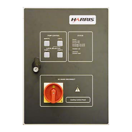
Section 2 Installation / Initial Turn-On ATLAS Analogue The included CD-ROM (971-0022-001) contains: 1. Transmitter control software files of the same revision as loaded into the transmitter at the factory 2. ISP (In-System Programming) software application which is used to install software upgrades into the transmitter controllers. - Page 33 Section 2 Installation / Initial Turn-On ATLAS Analogue NOTE: Two different Cooling Control Panel sizes have been produced. See Table 2-2 on page 2-5 for the corresponding drawing number of the Cooling System Electrical Diagram. Table 2-1 Model-Specific Documentation Numbers...
-
Page 34: Installation Checkboxes
Section 2 Installation / Initial Turn-On ATLAS Analogue Installation Checkboxes Located to the left of each important step in the installation procedure is a checkbox like the one to the left of this paragraph. As each step in the procedure is completed, the box should be checked. -
Page 35: Cooling System Installation
Electrical Installation Diagram b. AC Power Flow Diagram c. Cooling System Electrical Diagram NOTE: Two versions of the Cooling Control panel are utilized in the Atlas Analogue transmitter line. Table 2-2 Cooling Control Panel Sizes and Drawing Numbers Cooling System... - Page 36 NOTE: If any of these restrictions cannot be met, a site-specific modification may be required. Contact your Harris representative for modifications. c. It is recommended to have the front of the cooling control panel visible while standing in front of the transmitter.
- Page 37 Section 2 Installation / Initial Turn-On ATLAS Analogue a. Lift the unit into a horizontal position using manufacturer’s recommended lifting points b. Install the leg channels and brace angles c. Carefully place assembled unit onto concrete pad d. Fasten unit to the concrete pad Install safety warning labels.
-
Page 38: Large Cooling Control Panel Wiring
Section 2 Installation / Initial Turn-On ATLAS Analogue 2.5.1 Large Cooling Control Panel Wiring NOTE: Two different Cooling Control Panel sizes have been produced (see Table 2-2 on page 2-5). If your panel size measures 500x500x200 mm, refer to drawing 843- 5396-959 for the next four procedures, then continue with the section called "2.5.3 Continue Cooling System Installation"... - Page 39 Section 2 Installation / Initial Turn-On ATLAS Analogue Table 2-3 Pump Module Control and Status Connections Cooling Control Pump Module Panel X2-15 X1-15 X2-16 X1-16(GND) These connections should be verified using supplied schematics. DVA10000 Pump Module Panel Terminal X1 Connections NOTE: Terminal ID numbers may not be in order.
- Page 40 Section 2 Installation / Initial Turn-On ATLAS Analogue NOTE: Condensation can occur in the conduit leading to the outside heat exchanger from the control panel. This conduit should be caulked or sealed after the system is tested and operational. Table 2-4...
-
Page 41: Early Model Cooling Control Panel Wiring
Section 2 Installation / Initial Turn-On ATLAS Analogue 2.5.2 Early Model Cooling Control Panel Wiring NOTE: Two different Cooling Control Panel sizes have been produced (see Table 2-2 on page 2-5). If your panel size measures 400x300x150 mm, refer to drawing 843- 5396-865 for the following three procedures, then continue with the section called "2.5.3 Continue Cooling System Installation"... - Page 42 Section 2 Installation / Initial Turn-On ATLAS Analogue Table 2-5 Pump Module Control and Status Connections Cooling Control Pump Module Panel X2-25 X1-12 X2-26 X1-13 X2-27 X1-14 X2-28 X1-15 These connections should be verified using supplied schematics. DVA10000 Pump Module Panel Terminal X1 Connections NOTE: Terminal ID numbers may not be in order.
- Page 43 Section 2 Installation / Initial Turn-On ATLAS Analogue DVA1000 Heat Exchanger Panel Terminal X1 Connections NOTE: Terminal ID numbers may not be in order. NOTE: Condensation can occur in the conduit leading to the outside heat exchanger from the control panel. This conduit should be caulked or sealed after the system is tested and operational.
-
Page 44: Continue Cooling System Installation
Section 2 Installation / Initial Turn-On ATLAS Analogue 2.5.3 Continue Cooling System Installation Connect the control and status wires between the cooling control panel and the transmitter with the supplied multi-conductor cable. These low level signals connect from terminals X2-1 through X2-12 in the cooling control panel to J12-1 through J12-12 on the External I/O board in the transmitter (pin for pin connection). - Page 45 Section 2 Installation / Initial Turn-On ATLAS Analogue If there is a temperature overload switch on the test load, (as would be the case for an air cooled load) it should be connected to J18-11 and J18-12. This open interlock contact will mute the transmitter RF output if the test load temperature threshold is exceeded (while the transmitter is operating into the test load).
-
Page 46: Transmitter Ac Connection
A safety ground wire is required and connects to E2 which is shown in Figure 2-2 on page 2-17. The Atlas Analogue transmitters are 3 phase 208/220/240Vac or 3 phase 380/400/ 415Vac at 50/60Hz delta or wye. If voltage variations in excess of ±10% are anticipated, the transmitter power input must be equipped with automatic voltage regulators (optional equipment) capable of correcting the mains voltage. - Page 47 Section 2 Installation / Initial Turn-On ATLAS Analogue terminal block clamp in order to insert the cable. Release the clamp to secure the cable firmly in place. Connect the safety ground wire to TB5. Connect AC safety ground to smaller terminal located nearest to sidewall.
-
Page 48: Signal And Ground Connections
Section 2 Installation / Initial Turn-On ATLAS Analogue Signal and Ground Connections NOTE: Control and signal wires should never be run in the same conduit with any AC wiring. A separate conduit should be used for control and signal cables. -
Page 49: Intercabinet Connections
Section 2 Installation / Initial Turn-On ATLAS Analogue Intercabinet Connections For multi-cabinet transmitter models DVA20000 and DVA30000, the intercabinet connections will need to be installed next. See Intercabinet Wiring Diagram for reference. External Interlock Connections The transmitter has inputs for up to four external interlocks on the External I/O Board. -
Page 50: Initial Cooling System Turn On
Section 2 Installation / Initial Turn-On ATLAS Analogue 2.11 Initial Cooling System Turn ON NOTE: For further Cooling System start up information see the Transcool technical man- ual and Appendix B Cooling System Help section. Verify trip levels for the Pump Module pumps and Heat Exchanger fans inside the Cooling Control Panel. - Page 51 Section 2 Installation / Initial Turn-On ATLAS Analogue Table 2-7 Pump and Fan Trip Settings - Typical Atlas Transmitter 208/220/240 VAC Mains 380/400/415 VAC Mains DVA2500 or DVA5000 Pump Module (for each) 8.0A 4.3A Fan (for each) 1.4A 0.8A DVA10000 Pump Module (for each) 11.6A...
- Page 52 Section 2 Installation / Initial Turn-On ATLAS Analogue CAUTION: IF FREEZING CONDITIONS EXIST DURING CHECKOUT AND FLUSHING PROCEDURES, THE FLUSHING PROCEDURE AND SUBSEQUENT FILL WITH FINAL GLYCOL/WATER MUST BE FINISHED BEFORE STILL WATER IS ALLOWED TO REMAIN IN HEAT EXCHANGER. IF PROCEDURE CANNOT BE FINISHED, CARE MUST BE TAKEN TO PREVENT WATER FROM FREEZING IN OUTSIDE COOLING SYSTEM EQUIPMENT.
- Page 53 Section 2 Installation / Initial Turn-On ATLAS Analogue Verify correct pump rotation: Turn OFF pump isolator switch and observe the pump rotation window (see picture) as pump spins down. • If rotation is opposite of window arrow, Turn off primary AC power...
-
Page 54: Initial System Leak Tests
Section 2 Installation / Initial Turn-On ATLAS Analogue Verify remaining Heat Exchanger fan rotation. Repeat above step for 2nd (and 3rd if used) fan. 2.11.1 Initial System Leak Tests Turn on pump A for several minutes. Upon the establishment of a steady (no air bursts) volume of water throughout the system, begin visual check for leaks. -
Page 55: Initial System Flushing
Section 2 Installation / Initial Turn-On ATLAS Analogue of a trisodium phosphate-based detergent, such as Cascade, in 2 gallons of water), proceed with the following steps. Strain mixture into tank through a fine filter. Run the system for 1 hour. Alternate pumps A and B for 30 minutes each. -
Page 56: Final Cooling System Fill
Section 2 Installation / Initial Turn-On ATLAS Analogue • Open test load supply and return line valves. • Close cabinet(s) bypass valve(s). 2.11.4 Final Cooling System Fill CAUTION: THE SYSTEM MUST BE TESTED FOR LEAKS AGAIN ONCE THE REQUIRED 50/50 GLYCOL/WATER MIXTURE HAS FILLED THE ENTIRE SYSTEM. - Page 57 Section 2 Installation / Initial Turn-On ATLAS Analogue module, and heat exchanger. To approximate the volume of interconnection plumbing line use Table 2-9 to Table 2-9 Line Length to Capacity Conversion Factors Nominal Type M Feet to Gallons Feet to Liters...
-
Page 58: Install Pa Modules
Section 2 Installation / Initial Turn-On ATLAS Analogue 2.12 Install PA Modules Be sure the PA power supply breakers (on the mid deck in rear) are in the OFF position. WARNING: THE PA MODULES ARE LARGE AND RELATIVELY HEAVY, WEIGHING SLIGHTLY LESS THAN 25KG. - Page 59 PERATURE. DO NOT TOUCH THE MODULES WITH BARE HANDS AFTER THE TRANSMITTER HAS BEEN RUNNING. SPECIAL GLOVES HAVE BEEN PROVIDED IN THE REAR OF THE CABINET OR CAN BE OBTAINED FROM HARRIS, PART #0990006483 OR GRAINGER ITEM #4JF36. Verify all drain valves are closed and make sure all coolant system gate valves are open before proceeding with the initial turn on.
-
Page 60: Initial Turn-On
Section 2 Installation / Initial Turn-On ATLAS Analogue 2.13 Initial Turn-On Read and understand the entire initial turn-on procedure before starting. Detailed use of all GUI screens is given in Section 3 Operation. Shut off the front panel breaker. Apply 3 phase primary power to the transmitter. Be ready to quickly disconnect the power if necessary. - Page 61 Section 2 Installation / Initial Turn-On ATLAS Analogue Check the Low Voltage power supplies and AC Mains voltage. Press the POWER SUPPLY button then PS METERS to access the PS metering screen. Check for +15, -15 and +7.5 volts on LV PSU 1 and LV PSU 2, with the BUS voltage slightly lower. The AC Mains should read close to your measured AC voltage.
-
Page 62: Final Cooling System Turn On
Section 2 Installation / Initial Turn-On ATLAS Analogue two low voltage power supply units (LV PSU). The second exciter is optional. Press the BACK button to return to the System Setup screen. Set the Date, Time and LCD screen contrast. Press the CONTROL SET UP button. -
Page 63: Setting The Test Load Flow Switch Trip Level
Section 2 Installation / Initial Turn-On ATLAS Analogue 2.13.1.2 Setting the Test Load Flow Switch Trip Level Prepare to set the flow meter switch trip point. See documentation included with flow meter for procedure details. Adjust the test load coolant supply valve until the meter reads the correct flow rate shown in Table 2-10, or as indicated in Layout, Liquid Cooling System drawing. -
Page 64: Verifying Pump Switching
Section 2 Installation / Initial Turn-On ATLAS Analogue Verify the control settings and adjust if necessary. Inside the Heat Exchanger panel, verify that the control setting for the left (Fan A) and right (Fan B) thermostats are set at C and 38ºC, respectively, which will switch fan A on when the coolant temperature... -
Page 65: Rf Initial Turn On
Section 2 Installation / Initial Turn-On ATLAS Analogue NOTE: Exciter A is always factory installed as the lower unit, below the control panel. The optional exciter B is installed as the top unit just below the RFU, above the transmitter control panel (see layout photos on page 1-2). - Page 66 Section 2 Installation / Initial Turn-On ATLAS Analogue Verify that the reflected power at each PA module is under 50 watts. The PA Meters screen shows the forward and reflected power for each PA Module. Press the BACK button. All PAs should show a green (OK) status indication on the GUI (Power Amp screen).
- Page 67 Section 2 Installation / Initial Turn-On ATLAS Analogue been automated and is done with the press of a button, and only takes a few seconds. NOTE: This procedure should be initially be done every 2 weeks for the first 2 months of operation.
-
Page 68: Parallel Remote Control Connections
Section 2 Installation / Initial Turn-On ATLAS Analogue 2.14 Parallel Remote Control Connections Once proper operation of the transmitter has been initiated, remote control connections can be made. The following tables list the connectors and their corresponding signal names and functions. - Page 69 Section 2 Installation / Initial Turn-On ATLAS Analogue momentary ground switching and require the remote control equipment to sink at least 15mA to activate the function. The Pinouts of J13 and J14 are listed in Table 2-11. Table 2-11 J13 & J14, External I/O Board, Remote Control Connectors...
- Page 70 Section 2 Installation / Initial Turn-On ATLAS Analogue 2.15 Remote Status Outputs, J15 & J16 All of the remote status outputs are open collector and will sink 100mA at up to +24Vdc to provide an indication status is active. The pull up supply voltage for the status indications can be supplied via J15 &...
- Page 71 Section 2 Installation / Initial Turn-On ATLAS Analogue Table 2-12 J15 & J16, External I/O Board, Remote Status Outputs Connector Schematic Label Status Output Status Type and Polarity and pin # J15-2 +5VDC_ISOLATED Output: Install jumper to J15-11 to use internal supply for status pull ups.
-
Page 72: Remote Power Metering, J17
Section 2 Installation / Initial Turn-On ATLAS Analogue 2.15.1 Remote Power Metering, J17 Each analog metering output will provide 0 - 4.096Vdc output into a 400 ohm load (where 3Vdc = Full Scale). The connections for J17 are listed in Table 2-13. - Page 73 Section 2 Installation / Initial Turn-On ATLAS Analogue 7/26/05 888-2523-001 2-43 WARNING: Disconnect primary power prior to servicing.
- Page 74 Section 2 Installation / Initial Turn-On ATLAS Analogue 2-44 888-2523-001 7/26/05 WARNING: Disconnect primary power prior to servicing.
-
Page 75: Operation
ATLAS Analogue Section 3 Operation Introduction This section gives detailed operational information for the Atlas Analogue Solid-State UHF TV transmitter. Information will pertain mostly to the operation and navigation of the Graphical User interface (GUI) Touchscreen display. NOTE: Operation of the TVS-D660 exciter is covered in a two separate manuals which came with the transmitter. -
Page 76: Main Menu "Quick" Buttons
Section 3 Operation ATLAS Analogue Figure 3-1 Transmitter Control Panel NOTE: A similar set of GUI screens is available via web browser with an ethernet net- work connection and the optional eCDi hardware interface. 3.2.1 Main Menu "Quick" Buttons Just to the right of the touchscreen, there are 5 hardware buttons which are part of the front panel overlay. -
Page 77: Graphical User Interface (Gui)
Section 3 Operation ATLAS Analogue NOTE: To differentiate these buttons from the ones which show up on the LCD display, these will be referred to as "Quick" buttons in the manual text. Graphical User Interface (GUI) The GUI ("Gooey") was designed to provide an intuitive interface into the transmitter control system. - Page 78 Section 3 Operation ATLAS Analogue a. ON, Standby, Fault OFF, ON/FB (transmitter foldback), PS MUTE, and RF MUTE status indication. • ON: Normal operating mode • Standby: Transmitter turned off manually or remotely • Fault OFF: Transmitter forced off due to fault condition •...
-
Page 79: Gui Home Page
Section 3 Operation ATLAS Analogue GUI Home Page The HOME screen shown in Figure 3-3 is the primary operator screen and the default screen after boot up. The HOME screen contains the most important general operator information such as: a. System Forward and Reflected power b. - Page 80 Section 3 Operation ATLAS Analogue The quickest way to access the HOME screen is to press any of the 5 hardware buttons to the right of the display as there is a HOME button on each of those main menu screens, There are always five touchscreen navigation buttons on the right side of the display.
-
Page 81: Drive Chain Main Menu
Section 3 Operation ATLAS Analogue Drive Chain Main Menu If you press the Drive Chain button on the control panel overlay, or the Drive Chain button on the HOME screen, it will take you to the screen shown in Figure 3-4. The Drive Chain Menu structure is shown in Figure 3-37 on page 3-37. -
Page 82: Drive Chain Faults
Section 3 Operation ATLAS Analogue 1. Auto/Manual - This toggle button should always be in the Auto position for normal operation. Placing it in Manual mode prevents an autoswitch to the alternate drive chain. In AUTO mode, if the on-air drive chain drops below 50% of nominal power, or if the on-line exciter experiences a fault, the controller will automatically switch to the backup drive chain (if available). - Page 83 Section 3 Operation ATLAS Analogue NOTE: This screen is used for a procedure described in "5.5.3 RFU Calibration" on page 5-14, and is to be performed only by qualified service personnel if necessary. To Figure 3-4 Figure 3-6 RFU Setup Screen NOTE: Exciter A is always factory installed as the lower unit, below the control panel.
-
Page 84: Power Amp Main Menu
Disconnected - When a module is unplugged its icon turns gray NOTE: For multi-cabinet Atlas Analogue transmitters (DVA20000 and DVA30000) the cabinet select buttons are located at the bottom of the screen. The DVA20000 will have two cabinets to select from, and the DVA30000 will have three. Once the... -
Page 85: Pa Faults
Section 3 Operation ATLAS Analogue others cabinets’. Always be sure that you are accessing the desired cabinet number. To get detailed information on a particular PA Module, press the desired amplifier button in the middle of the screen. Any of these buttons will take you to the PA Faults screen shown in Figure 3-8. -
Page 86: Pa Meters
Section 3 Operation ATLAS Analogue Figure 3-9 More PA Faults Screen The left column indicates current faults. The center indicates transistor faults. 3.6.2 PA Meters This screen is accessed by pressing the "PA Meters" button in Figure 3-7. This screen gives detailed PA metering by PA Cabinet. - Page 87 Section 3 Operation ATLAS Analogue To Figure 3-11 Figure 3-10 PA Metering Screen PA Module will fault off at 100W "Prefld(W)" reflected power. Also, it will fault off at 70° C temperature. NOTE: The PA output powers displayed under the PA Meters heading are not peak sync power, but the power at blanking level.
-
Page 88: Pa Service
Section 3 Operation ATLAS Analogue When taking readings, be sure to note the PA Module Number and Cabinet Number Figure 3-11 More PA Meters Screen PA Module will fault off with any of the following maximum temperatures shown under the Module Temperatures heading: "Heatsink" @ 70°C; "PS Bd" @ 95°C;... -
Page 89: Pa Module Removal
Section 3 Operation ATLAS Analogue To Figure 3-13 To Figure 3-14 To Figure 3-7 Figure 3-12 PA Service Screen 3.6.3.1 PA Module Removal This screen is simply intended as a quick reference of the proper way to remove and install a PA module. -
Page 90: Pa Module Alignment - "Auto Bias
Section 3 Operation ATLAS Analogue 3.6.3.2 PA Module Alignment - "Auto Bias" This screen is accessed by pressing the "PA Align" button in Figure 3-12. This screen allows the bias on the individual PA module pallets to be optimized. This procedure should only be done after the transmitter has been operating at nominal power output, in an average ambient temperature, for at least one hour. - Page 91 Section 3 Operation ATLAS Analogue ing temperature it may be an indication that the PA Module Alignment needs to be performed. 7/26/05 888-2523-001 3-17 WARNING: Disconnect primary power prior to servicing.
-
Page 92: Output Main Menu
Section 3 Operation ATLAS Analogue Output Main Menu If you press the Output button on the control panel overlay, or the Output button on the HOME screen, it will take you to the screen shown in Figure 3-15. The Output Menu structure is shown in Figure 3-39 on page 3-38. -
Page 93: Output Faults
Section 3 Operation ATLAS Analogue the appropriate connection on the External I/O board must be jumpered. For more information see "2.9 External Interlock Connections" on page 2-19. 3.7.1 Output Faults This screen shows faults which are considered Cabinet or System level such as VSWR, Power High, foldback etc... -
Page 94: Output Service
Section 3 Operation ATLAS Analogue To Figure 3-15 Figure 3-17 Output Metering Screen (DVA30000 Shown) 3.7.3 Output Service This screen is accessed from the Output System screen in Figure 3-15. It is an intermediate menu screen which explains the purpose of the PA Reject Service and Output Setup screens. -
Page 95: Pa Reject Service
Section 3 Operation ATLAS Analogue 3.7.3.1 PA Reject Service This screen shows the relative power at each of the PA module combiner reject loads. This screen should only be accessed by engineering personnel. For the proper phasing sequence refer to "5.4 PA Module Phasing" on page 5-6. -
Page 96: Power Supply Main Menu
Section 3 Operation ATLAS Analogue Power Supply Main Menu If you press the Power Supply button on the control panel overlay, it will take you to the screen shown in Figure 3- 20. The Power Supply Menu structure is shown in Figure 3-40 on page 3-38. -
Page 97: Ps Faults
Section 3 Operation ATLAS Analogue 3.8.1 PS Faults This screen is Power Supply status screen which lists of all of the monitored power supply faults for the AC Mains and Low Voltage Power Supplies. An active fault will be highlighted in RED, while a warning condition will be highlighted in YELLOW. For a detailed explanation of these faults, refer to Section 6, Diagnostics. -
Page 98: System Main Menu
Section 3 Operation ATLAS Analogue System Main Menu If you press the System button on the control panel overlay, it will take you to the screen shown in Figure 3- SYSTEM 23. The System Menu structure is shown in Figure 3-41 on page 3-39. -
Page 99: Control System Main Menu
Section 3 Operation ATLAS Analogue d. System Service - Gives visual carrier frequency and selected channel number. Pressing "System Service" gives access to configuration, touchscreen calibration, software and hardware revisions, time and date setting, screen saver timeout and LCD display contrast. -
Page 100: Cooling System Main Menu
Section 3 Operation ATLAS Analogue 3.9.2 Cooling System Main Menu The following screen is the Cooling System Main Menu. It shows status, metering and faults for the cooling system. It also provides for automatic or manual control of pump switching and tells which pump is active. -
Page 101: Cooling Faults
Section 3 Operation ATLAS Analogue To Figure 3-26 Press button to access Cooling Faults screen To Figure 3-27 (Press desired cabinet icon for multi-cabinet To Figure 3-28 transmitters) To Figure 3-23 Figure 3-25 Cooling System Screen (DVA30000 Shown) 3.9.2.2 Cooling Faults This screen is accessed by pressing either of the Cooling Faults buttons on the System Cooling screen. -
Page 102: Cooling Meters
Section 3 Operation ATLAS Analogue 3.9.2.3 Cooling Meters This screen is accessed by pressing the Cooling Meters button on the System Cooling screen. It reads out Coolant flow, Coolant Inlet and Outlet temperature, and Cabinet air temperature. Units given are typical for a DVA10000. -
Page 103: System Log
Section 3 Operation ATLAS Analogue To Figure 3-25 Figure 3-28 Cooling Service Screen 3.9.3 System Log This screen is accessed by pressing the System Log button on the System screen in Figure 3-23 on page 3-24. It is a complete listing of all transmitter and system faults in the order in which they occurred. -
Page 104: System Service
Section 3 Operation ATLAS Analogue Note: Date format is DD/MM/YY Press to clear all faults To Figure 3-23 Figure 3-29 System Log Screen 3.9.4 System Service This screen is accessed by pressing the System Service button in Figure 3-23 on page 3- 24. -
Page 105: System Setup
Section 3 Operation ATLAS Analogue To Figure 3-31 To Figure 3-35 To Figure 3-36 To Figure 3-23 Figure 3-30 System Service Screen 3.9.4.1 System Setup This screen provides a way to change 3 important pieces of information which are then used throughout the GUI. -
Page 106: Control Setup
Section 3 Operation ATLAS Analogue • AC Line Frequency: Should reflect your line frequency - 50Hz or 60Hz • Exciters: Select number of exciters for this system • Output Switch: Selects Manual or Motor output switching • Cooling Pumps: Select number of cooling pumps for this system... -
Page 107: Touch Screen Calibration
Section 3 Operation ATLAS Analogue To Figure 3-33 To Figure 3-31 Figure 3-32 Control Setup Screen 3.9.4.1.1 Touch Screen Calibration If the touch screen soft buttons on the GUI are working and seem to be accurate, then this procedure is not required. If the soft buttons on the touch screen do not seem to... - Page 108 Section 3 Operation ATLAS Analogue NOTE: The procedure can be aborted by pressing any of the 5 hardware Quick keys on the control panel. Figure 3-33 Touchscreen Calibration Screens Figure 3-34 Touchscreen Calibration Test Screen 3-34 888-2523-001 7/26/05 WARNING: Disconnect primary power prior to servicing.
-
Page 109: Software Revisions (Sw Revs)
Section 3 Operation ATLAS Analogue 3.9.4.2 Software Revisions (SW REVs) This screen shows the software revision for all transmitter controllers and PA module controllers. This information should be known before calling for technical support. To Figure 3-30 Figure 3-35 Software Revisions Screen 3.9.4.2.1 Hardware Revisions... -
Page 110: Gui Menu Structures
HOME Page. Each successive level represents the software buttons which will show up on the right side of the GUI. NOTE: Multi-cabinet Atlas Analogue transmitters will require an extra button press at the top level menu to select the desired cabinet. 3-36... - Page 111 Section 3 Operation ATLAS Analogue DRIVE CHAIN Main Menu Drive Drive Drive Service Faults Meters Exciter Status Setup Figure 3-37 Drive Chain Menu Structure POWER Main Menu Faults Meters Service PA Module More PA More PA PA Module Alignment Meters...
- Page 112 Section 3 Operation ATLAS Analogue OUTPUT Main Menu Output Output Output Faults Meters Service REFL PA Reject Service Figure 3-39 Output Menu Structure POWER SUPPLY Main Menu Faults Meters Figure 3-40 Power Supply Menu Structure 3-38 888-2523-001 7/26/05 WARNING: Disconnect primary power prior to servicing.
- Page 113 Section 3 Operation ATLAS Analogue SYSTEM Main Menu System Cooling Control System System Service System Cooling Cooling System Hardware Software Cooling Meters Revision Service Setup Faults Control Setup Touch Screen Calibration Figure 3-41 System Menu Structure 7/26/05 888-2523-001 3-39 WARNING: Disconnect primary power prior to servicing.
- Page 114 Section 3 Operation ATLAS Analogue 3-40 888-2523-001 7/26/05 WARNING: Disconnect primary power prior to servicing.
-
Page 115: Theory Of Operation
ATLAS Analogue Section 4 Theory of Operation Introduction This section contains detailed descriptions of the Atlas Series transmitter and its internal sub-assemblies and any pertinent information regarding the external assemblies such as the pump module and heat exchanger. The rest of this section will be broken up into 4 main topics: •... -
Page 116: Block Diagram Descriptions
Also, as part of our standard practice, the first page of a PC board schematic is also a block diagram of that board. Table 4-1 gives the basic Atlas model numbers and configurations. Table 4-1 Atlas Analogue Transmitter Models Tx Models Cabinets PA Modules... -
Page 117: Micro Module
Section 4 Theory of Operation ATLAS Analogue G ra p h ic a l U s e r In te rfa c e G ra p h ic a l U s e r In te rfa c e L o c a l P u s h b u tto n C o n tro ls... -
Page 118: Cpld, Complex Programmable Logic Device
Section 4 Theory of Operation ATLAS Analogue Features of the 376 module include: a. Built-in CAN (Controller Area Network) bus controller b. 16 A/D inputs for analog metering c. A serial EEPROM for non-volatile memory storage d. A built in clock running at 4.194MHz which will let the micro run at 16-25MHz e. -
Page 119: Life Support Backup
Section 4 Theory of Operation ATLAS Analogue control system. If the micro module wants to send a control command, it simply addresses the correct I/O line on the CPLD and it then sends out the command. 4.3.2.2 Life Support Backup The CPLD monitors the watchdog circuit or more specifically the RESET line on the micro module. -
Page 120: System Control Bus
Section 4 Theory of Operation ATLAS Analogue the single ended CAN controller to the differential CAN bus for high common mode noise immunity, as shown in Figure 4-2. All of the control boards can send and receive information over the differential CAN bus, however the Main Controller determines what information is sent and when it is sent for this application. -
Page 121: Parallel Control Lines
Section 4 Theory of Operation ATLAS Analogue 4.3.4.1 Parallel Control Lines The parallel control lines are used for quick actuation of critical functions, such as ON, OFF, RF mute, PS mute, AC_Low and Fault Off. These lines are also the backup control lines in Life Support mode when the Main Controller (and therefore the CAN bus) is not operational. -
Page 122: Main Controller
Section 4 Theory of Operation ATLAS Analogue e. /PS_MUTE The /PS_MUTE line shuts down the output of the 32 Volt PA module supplies temporarily until the fault condition is cleared. This is a non-latching signal. The Main Controller, Power Block Controller, External I/O and RF Monitor Boards monitor this line and have the ability to activate it if necessary. -
Page 123: Transmitter Control
1 serial port, J90, is available for operator connection to run the In-System Programming or ISP software, supplied by Harris, to update the software for the Main Controller and/or any other micro in the transmitter. -
Page 124: Life Support Mode, Main Controller
These switches are for: • Micro RESET, S2 • RF SEL, S4 - Not used in Atlas Analogue transmitter • Pump Select, S5. This switch is labeled PUMP SEL. This will select the alternate coolant pump in the pump module. -
Page 125: Manual Rf Mute
Section 4 Theory of Operation ATLAS Analogue NOTE: To switch between the A or B RF Drive chain, press the Drive Switch (blue but- ton) on the front panel of the RFU. The corresponding LED will illuminate. 4.3.5.4 Manual RF MUTE The Main Controller has a toggle switch, S3 which can be used to mute the transmitter RF output without shutting it off. -
Page 126: External Interlocks
Section 4 Theory of Operation ATLAS Analogue 1. One (1) is connected directly to the serial port on the micro-module and is used for VT-100 diagnostics and for ISP (In-System Programming). 2. Two (2) are for connection to an external computer or modem for serial remote control applications (applications provided by customer). -
Page 127: Rf Mute Interlock
Section 4 Theory of Operation ATLAS Analogue transmitter will be shut off. If the external interlock is not going to be used, all 6 jumpers must be installed, effectively connecting J18-1 to ground to allow the transmitter to turn on. -
Page 128: Transmitter Rf System
Section 4 Theory of Operation ATLAS Analogue Transmitter RF System 4.4.1 TVS-D660 Exciter(s) The Atlas transmitter comes standard with a single TVS-D660 exciter. A second standby exciter is available as an option along with an exciter changeover switch in the RF Unit (RFU). -
Page 129: Rf Detectors
Section 4 Theory of Operation ATLAS Analogue a. Communicating with the System Controller via the internal Controller Area Net- work bus b. Monitoring the power into the reject power loads from the modules c. Monitoring system and cabinet forward RF power d. -
Page 130: Reject Load Rf Detector (Relative)
Section 4 Theory of Operation ATLAS Analogue j. Precision RF power measurement #3 System Forward Power k. Precision RF power measurement #4 System Reflected Power l. Precision RF power measurement #5 Drive Chain A Power m. Precision RF power measurement #6 Drive Chain B Power 4.4.3.2... -
Page 131: Pa Module Phase Alignment
Section 4 Theory of Operation ATLAS Analogue The detectors do not have perfect frequency response over the entire UHF band. Therefore, to eliminate calibration requirements, the detector Output Voltage vs. Frequency was characterized and the results used to generate a lookup table to set the thresholds for the fault comparators. -
Page 132: Normal Mode / Life Support Mode
Section 4 Theory of Operation ATLAS Analogue GOAL: To get the Reject Loads detected RF Detected RF sample sample level level, 0000 - 1023 readings below 0030 (with Gain set to LOW) Module Group select buttons PA Module Phase Control Voltage... -
Page 133: Backplane Interface Board
Section 4 Theory of Operation ATLAS Analogue 4.4.4 Backplane Interface Board The Backplane Interface Board is accessed from the rear of the transmitter and is located just above the PA Module compartment. Its function is to distribute RF, low voltage and control signals to the PA modules. -
Page 134: Pa Module
4.4.5 PA Module The Atlas Analogue PA Module is a wideband, high gain, liquid cooled RF amplifier. Each PA module has a maximum RF output of 1435W peak sync power with a liquid cooled heatsink. The number of PA modules is determined by the transmitter power level or model and is given in Table 4-1.
Need help?
Do you have a question about the ATLAS ANALOGUE and is the answer not in the manual?
Questions and answers