Chapters
Table of Contents
Troubleshooting

Related Manuals for Harris APEX


Summary of Contents for Harris APEX
- Page 1 TECHNICAL MANUAL APEX Exciter Incorporating FLO Technology 888-2604-001 T.M. No. 888-2604-001 Printed: January 25, 2007 Revision A, 03/08/07 © Copyright Harris Corporation 2007 All rights reserved...
- Page 2 TELEX service (650/372-2976). Replaceable Parts Service Replacement parts are available 24 hours a day, seven days a week from the HARRIS Service Parts Department. Telephone 217/222-8200 to contact the service parts department or address correspondence to Service Parts Department, HARRIS CORPORATION, Broadcast Systems Division, P.O.
- Page 3 ™ ™ APEX Exciter Incorporating FLO Technology MANUAL REVISION HISTORY APEX™ Exciter Incorporating FLO™ Technology 888-2604-001 Rev. Date Pages Affected 3/8/07 54395 Released Manual March 8, 2007 888-2604-001 Page: i WARNING: Disconnect primary power prior to servicing.
- Page 4 ™ ™ APEX Exciter Incorporating FLO Technology Page: ii 888-2604-001 March 8, 2007 WARNING: Disconnect primary power prior to servicing.
- Page 5 C001 and is not the actual part number for C001. In the ten digit part numbers, if the last three numbers are 000, the item is a part that Harris has purchased and has not manufactured or modified.
- Page 6 ™ ™ APEX Exciter Incorporating FLO Technology Page: iv 888-2604-001 March 8, 2007 WARNING: Disconnect primary power prior to servicing.
- Page 7 The installation, operation, maintenance and service of this equipment involves risks both to personnel and equipment, and must be performed only by qualified personnel exercising due care. HARRIS CORPORATION shall not be responsible for injury or damage resulting from improper procedures or from the use of improperly trained or inexperienced personnel performing such tasks.
- Page 8 ™ ™ APEX Exciter Incorporating FLO Technology Page: vi 888-2604-001 March 8, 2007 WARNING: Disconnect primary power prior to servicing.
- Page 9 ™ ™ APEX Exciter Incorporating FLO Technology FIRST-AID Personnel engaged in the installation, operation, maintenance or servicing of this equipment are urged to become familiar with first-aid theory and practices. The following information is not intended to be complete first-aid procedures, it is a brief and is only to be used as a reference.
- Page 10 ™ ™ APEX Exciter Incorporating FLO Technology Page: viii 888-2604-001 March 8, 2007 WARNING: Disconnect primary power prior to servicing.
-
Page 11: Table Of Contents
™ ™ APEX Exciter Incorporating FLO Technology Table of Contents Table of Contents Introduction ........1-1 Organization of Technical Manual . - Page 12 ™ ™ APEX Exciter Incorporating FLO Technology Table of Contents Details of the Exciter Status Screens....3-8 3.4.1 System Status Screen ......3-8 3.4.2...
- Page 13 Transmitter Systems Block Diagram....4-1 APEX Exciter Digital Assembly Overview ....4-2 4.3.1...
- Page 14 4.3.3 Exciter Output Spectral Response, RTAC Bypassed ...4-6 APEX Exciter Analog Assembly Overview ....4-7 4.4.1 Up Converter Board Block Diagram Description.
- Page 15 ™ ™ APEX Exciter Incorporating FLO Technology Table of Contents Default Settings For DIagnostics Screens ....5-10 Typical Settings for the More Critical Exciter Setups ...5-11 Exciter Troubleshooting Flow Charts .
- Page 16 ™ ™ APEX Exciter Incorporating FLO Technology Table of Contents Page: xiv 888-2604-001 03/08/07 WARNING: Disconnect primary power prior to servicing.
- Page 17 Rear Panel View APEX Exciter Incorporating FLO Technology ..1-2 Figure 1-2 APEX Exciter Front Panel View ......1-3 Figure 2-1 Exciter Inputs and Outputs .
- Page 18 APEX Exciter/ Transmitter - RF Interconnection Block Diagram ..4-2 Figure 4-2 APEX Exciter - Signal Flow Block Diagram ....4-4 Figure 4-3 The 44.4 MHz Phase Lock Loop .
- Page 19 ™ ™ APEX Exciter Incorporating FLO Technology List of Figures Figure A-1 Tera Term Pro Screen When Connected to Exciter ....A-2 Figure A-2 Stop Action Capture of Screen Down Load Scroll....A-2 Figure A-3 Tera Term Log Window Selected When Download Has Completed .
- Page 20 ™ ™ APEX Exciter Incorporating FLO Technology List of Figures Page: xviii 888-2604-001 03/08/07 WARNING: Disconnect primary power prior to servicing.
- Page 21 List of Tables Table 1-1 Harris APEX Exciter General Specifications ....1-4 Table 1-2 Harris APEX Exciter Service Conditions Specifications ... . . 1-5 Table 1-3 Harris APEX Exciter Performance Specifications .
- Page 22 ™ ™ APEX Exciter Incorporating FLO Technology List of Tables Page: xx 888-2604-001 03/08/07 WARNING: Disconnect primary power prior to servicing.
-
Page 23: Introduction
• Section 5 - Maintenance and Troubleshooting, describes checks and test which may be used to isolate a suspected problem in the exciter. • Section 6 - Parts List, is an indexed listing of field-replaceable parts for the APEX ex- citer. -
Page 24: Physical Description
Physical Description Physical Description The APEX exciter consists of a single rack mounted chassis with the analog section available from the top of the exciter and the digital section available from the bottom. The exciter is normally mounted in the transmitter on slides, permitting it to be extended forward out of the cabinet for service. -
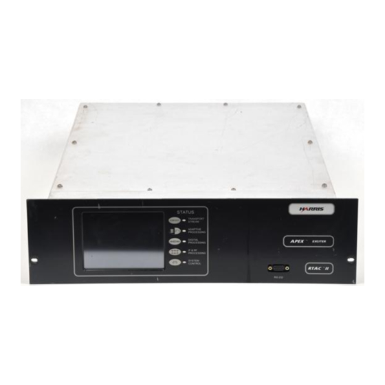
Page 25: Figure 1-2 Apex Exciter Front Panel View
™ ™ APEX Exciter Incorporating FLO Technology Physical Description Introduction Figure 1-2 APEX Exciter Front Panel View 03/08/07 888-2604-001 Page: 1-3 WARNING: Disconnect primary power prior to servicing. -
Page 26: Technical Overview
RTAC circuits. Specifications Specifications for the exciter are listed in Tables 1-1, 1-2, and 1-3. Note Specifications subject to changed without notice. Table 1-1 Harris APEX Exciter General Specifications Specification Explanation RF output connector SMA, 50 ohm impedance... -
Page 27: Table 1-2 Harris Apex Exciter Service Conditions Specifications
Antenna connection is an active input with +5V on the center conductor. Signal frequency is 1575.42 MHz, level can range from -133 to -115 dBm, input impedance is 50 ohms. Table 1-2 Harris APEX Exciter Service Conditions Specifications Specification Explanation Ambient temperature 0°... -
Page 28: Table 1-3 Harris Apex Exciter Performance Specifications
™ ™ APEX Exciter Incorporating FLO Technology Introduction Specifications Table 1-3 Harris APEX Exciter Performance Specifications Specification Explanation Maximum power output 1 watt peak, 250 mW average Power output range Programable 1 to 250 mW average Regulation of output power... -
Page 29: Installation
™ ™ APEX Exciter Incorporating FLO Technology Introduction Installation Installation Introduction Exciters sold as part of a transmitter will normally have been tested in the transmitter before shipment. The exciter may be removed for shipment, to be reinstalled after the trans- mitter is in place. -
Page 30: Ac Power
™ ™ APEX Exciter Incorporating FLO Technology Installation Installation of the GPS 1PPS Signal • PA SAMPLE IN (SMA) is the input signal connector for an RF sample from the out- put of the transmitter power amplifier, taken before the HPF and after the PA combin- er for transmitters with multiple PAs. -
Page 31: Retrofitting Into Existing Transmitter System
One of the most important aspects of installing the exciter into an existing transmitter consists of providing the APEX with the appropriate feedback signals. It is impractical to discuss every possible transmitter installation, the intent of this section is to provide enough information to the systems engineer to allow him to determine the optimum feedback arrangement. -
Page 32: Feedback Signal Quality Requirements
The required couplers are already installed in the main RF path for transmitter monitoring. These couplers can be used to provide the feedback samples to the APEX exciter. In the event that a given coupler is dedicated to a transmitter function, that sample can be split into two paths using a coupler, with the output port of the added coupler connected to the transmitter function input cable and the coupled port used for the APEX feedback signal. -
Page 33: Atlas Mobile Transmitters
The feedback signals at the exciter inputs should be padded to yield 0 dBm at the highest expected transmitter output power. The maximum input range is -30 to 0 dBm. Apex FLO Exciter RFU/... -
Page 34: Atlas Mobile Transmitter - 2 Or More Pa Cabinets
Figure 2-4 • The feedback signals at the exciter input should be padded to yield 0 dBm at the high- est expected transmitter output power. The sample input power range is -30 to 0 dBm. Apex FLO Exciter PA Cabinet... -
Page 35: Configuring The Exciter
Installation Configuring the Exciter The APEX exciter is configured by the LCD touch screens. The basic functions of these screens are discussed in chapter 3 of this manual. It is necessary to be familiar with these screens in order to configure the exciter. This procedure is only a configuration checklist. - Page 36 Main Screen > Setup > Display Setup. • Enter the Date and Time. • Enter a new page title, if something other then APEX Exciter is desired. • Chart selection allows the operator to view the Main screen response display at vari- ous points along the transmitter system.
-
Page 37: Configuration Of Status Screens
™ ™ APEX Exciter Incorporating FLO Technology Configuring the Exciter Installation This screen provides a means of changing the user and diagnostics passwords. The existing passwords can be determined by entering either the User or Diagnostic Password choices. The password becomes important if the User Setup or the Diagnostics Setup (or both) are to be locked. -
Page 38: Normal Settings For Diagnostic Screens
™ ™ APEX Exciter Incorporating FLO Technology Installation Configuring the Exciter 2.6.3 Normal Settings for Diagnostic Screens The Diagnostics screens offer tests used to diagnose exciter problems. If the diagnostic selections are left in the wrong states, normal operation of the exciter could be impaired. -
Page 39: Materials Needed
The coupled port has a 10 dB attenuation from the input. • Splitter, two port, Mini Circuits, ZFSC-2-2, zero phase, 50 ohm SMA, Harris part number 620-2964-000 This splitter is used to split a feedback signal to two exciters. - Page 40 ™ ™ APEX Exciter Incorporating FLO Technology Installation Materials Needed Page: 2-12 888-2604-001 03/08/07 WARNING: Disconnect primary power prior to servicing.
-
Page 41: Navigating The Lcd Display Screens
Navigating the LCD Display Screens Navigating the LCD Display Screens Operating the APEX exciter requires knowledge of two sets of controls. First is the power off/on switch, which is not normally used if the exciter is mounted in a transmitter, but could be used if the exciter is used as a signal source apart from a trans- mitter. -
Page 42: Starting Point: The Main Lcd Touch Screen
MainScreen.bmp Figure 3-1 LCD Main Screen Setup, operation, and trouble shooting of the APEX exciter is accomplished via the LCD Display Touch Screens. This chapter covers the use and definitions of the screens. When power is first applied, a power up screen appears briefly, but the display quickly changes to the main screen, shown in Figure 3-1. -
Page 43: Spectrum Response Screen
™ ™ APEX Exciter Incorporating FLO Technology Starting Point: The Main LCD Touch Screen Navigating the LCD Display Screens • RF spectrum display at selected locations throughout the transmitter RF system. Several Main screen soft keys are provided to start the process of navigation through the various LCD screens. -
Page 44: Flo Measure Soft Key
™ ™ APEX Exciter Incorporating FLO Technology Navigating the LCD Display Screens LCD Display Flow Chart 3.2.4 FLO Measure Soft Key The FLO Meas (measure) soft key at the top of the main screen provides information concerning the transmitter system distortions and exciter corrections for them. This infor- mation is given in three screens. -
Page 45: Figure 3-2 Apex Exciter Lcd Display Flow Chart, Main Screen
Note: Selecting Home from any screen returns to the Main Screen. Selecting Fault from any screen returns to the Exciter Status Screen. Figure 3-2 APEX Exciter LCD Display Flow Chart, Main Screen 03/08/07 888-2604-001 Page: 3-5 WARNING: Disconnect primary power prior to servicing. -
Page 46: Figure 3-5 System Status Screen
Screen 5 of 5 Front Panel Revisions CAN Status GPS Status See page 3-30 See page 3-30 See page 3-31 Figure 3-3 APEX Exciter LCD Display Flow Chart, Status Screens Page: 3-6 888-2604-001 03/08/07 WARNING: Disconnect primary power prior to servicing. - Page 47 Note: Selecting Home from any screen returns to the Main Screen. Selecting Fault from any screen returns to the Exciter Status Screen. Figure 3-4 APEX Exciter LCD Display Flow Chart, Setup Screens 03/08/07 888-2604-001 Page: 3-7 WARNING: Disconnect primary power prior to servicing.
-
Page 48: Details Of The Exciter Status Screens
™ ™ APEX Exciter Incorporating FLO Technology Navigating the LCD Display Screens Details of the Exciter Status Screens Details of the Exciter Status Screens SystemStatus.bmp Figure 3-5 System Status Screen This section provides pictures and details of the Exciter Status screen, shown in Figure 3-5, and its sub screens. -
Page 49: Transport Stream Status Screen
™ ™ APEX Exciter Incorporating FLO Technology Details of the Exciter Status Screens Navigating the LCD Display Screens 3.4.2 Transport Stream Status Screen TrnsStrmStatus.bmp Figure 3-6 Transport Stream Status Screen The Transport Stream Status screen is shown in Figure 3-6, with screen entries listed below. - Page 50 ™ ™ APEX Exciter Incorporating FLO Technology Navigating the LCD Display Screens Details of the Exciter Status Screens The Adaptive Processing Board status screen is shown in Figure 3-7, with screen entries listed below. • 3.3 Vdc: This is the output of the 3.3 V dc to dc converter.
-
Page 51: Adaptive Processing Diagnostics
™ ™ APEX Exciter Incorporating FLO Technology Details of the Exciter Status Screens Navigating the LCD Display Screens 3.4.3.1 Adaptive Processing Diagnostics AdaptPrecDiagnostics.bmp Figure 3-8 Adaptive Processing Diagnostics The Adaptive Processing Diagnostic screen is shown in Figure 3-8, with screen entries listed below. -
Page 52: Digital Processing Screens
™ ™ APEX Exciter Incorporating FLO Technology Navigating the LCD Display Screens Details of the Exciter Status Screens 3.4.4 Digital Processing Screens DigitalPrecStatus.bmp Figure 3-9 Modulation Board Status Screen The Digital processing Status selection offers two selections, which are: • The Modulator, which consists of screen 1, the FPGA Modulator, and screen 2, which gives the software revisions of the ADC &... -
Page 53: Adc And Dac Boards Status, Screen 2/2
™ ™ APEX Exciter Incorporating FLO Technology Details of the Exciter Status Screens Navigating the LCD Display Screens • 5 Vdc: This is the board input voltage, which comes from the controller board. • 3.3 Vdc: This is the output of the 3.3 V dc to dc converter. -
Page 54: Flo Fpga Status, Summary, Screen 1/5
™ ™ APEX Exciter Incorporating FLO Technology Navigating the LCD Display Screens Details of the Exciter Status Screens 3.4.4.3 FLO FPGA Status, Summary, Screen 1/5 FPGA Status1.bmp Figure 3-12 FLO FPGA Status, Summary, Screen 1/5 The parameters of the FPGA Summary screen are as follows. -
Page 55: Flo Fpga, Gps & Clock Status, Screen 2/5
™ ™ APEX Exciter Incorporating FLO Technology Details of the Exciter Status Screens Navigating the LCD Display Screens 3.4.4.4 FLO FPGA, GPS & Clock Status, Screen 2/5 FPGA Status2.bmp Figure 3-13 FLO FPGA, GPS & Clock Status, Screen 2/5 The parameters of the FPGA GPS & Clock Status screen are as follows. -
Page 56: Flo Fpga, Transport Stream Status, Screen 3/5
™ ™ APEX Exciter Incorporating FLO Technology Navigating the LCD Display Screens Details of the Exciter Status Screens 3.4.4.5 FLO FPGA, Transport Stream Status, Screen 3/5 FPGA Status3.bmp Figure 3-14 FLO FPGA, Transport Stream Status Screen 3/5 The parameters of the Transport Stream Status screen are as follows. -
Page 57: Flo Fpga, Sfn Fifo Status, Screen 4/5
™ ™ APEX Exciter Incorporating FLO Technology Details of the Exciter Status Screens Navigating the LCD Display Screens 3.4.4.6 FLO FPGA, SFN FIFO Status, Screen 4/5 FPGA Status4.bmp Figure 3-15 FLO FPGA, FSN FIFO Status, Screen 4/5 The parameters of the SFN FIFO Status screen are as follows. -
Page 58: Flo Fpga, Mti Status, Screen 5/5
™ ™ APEX Exciter Incorporating FLO Technology Navigating the LCD Display Screens Details of the Exciter Status Screens 3.4.4.7 FLO FPGA, MTI Status, Screen 5/5 FPGA Status5.bmp Figure 3-16 FLO FPGA, MTI Status, Screen 5/5 The parameters of the SFN FIFO Status screen are as follows. -
Page 59: If & Rf Processing Status Screens
™ ™ APEX Exciter Incorporating FLO Technology Details of the Exciter Status Screens Navigating the LCD Display Screens 3.4.5 IF & RF Processing Status Screens The IF & RF Processing Status selection contains four sub screens, which are: • UDC Interface Board, Screen 1 of 4 •... -
Page 60: Pll Board Status Screen
™ ™ APEX Exciter Incorporating FLO Technology Navigating the LCD Display Screens Details of the Exciter Status Screens 3.4.5.2 PLL Board Status Screen PLLStatus.bmp Figure 3-18 PLL Board Status Screen The PLL Board screen is shown in Figure 3-18, with screen entries listed below. -
Page 61: 3.4.5.2.1 Pll Diagnostics
™ ™ APEX Exciter Incorporating FLO Technology Details of the Exciter Status Screens Navigating the LCD Display Screens 3.4.5.2.1 PLL Diagnostics Refer to Figure 3-19. This screen is not used phase lock loop boards where the PLL Board 10 kHz Reference entry, shown in Figure 3-18, is labeled N/A. It is used for units where the PLL Board 10 kHz Reference entry is labeled Yes. -
Page 62: 3.4.5.3.1 Up Converter Diagnostics
™ ™ APEX Exciter Incorporating FLO Technology Navigating the LCD Display Screens Details of the Exciter Status Screens • 15 Vdc: Input power from UDC interface board via connector J3. • -15 Vdc: Input power from UDC interface board via connector J3. -
Page 63: Down Converter Board Status Screen
™ ™ APEX Exciter Incorporating FLO Technology Details of the Exciter Status Screens Navigating the LCD Display Screens • TuneB: (range 0 to 4095) The number in the TuneB window represents the dc voltage applied to the UHF tunable bandpass filter in the up converter. This voltage places the selected transmitting channel in the center of the bandpass of the filter. -
Page 64: 3.4.5.4.1 Down Converter Diagnostics
™ ™ APEX Exciter Incorporating FLO Technology Navigating the LCD Display Screens Details of the Exciter Status Screens These samples normally cycle through in two to four second steps. The sequence is HPF, Amplifier, and HPF. • Board Rev: This is the board revision for the Down Converter board. -
Page 65: System Control Status Screens
™ ™ APEX Exciter Incorporating FLO Technology Details of the Exciter Status Screens Navigating the LCD Display Screens • RF Sample AGC: (Enabled or Disabled), actually an APC, automatic power control. When enabled, the level of each RF sample (at the output of the down converter) is adjusted to the correct level required at the input of the ADC (analog to digital con- verter). -
Page 66: Controller Board Status Screen
™ ™ APEX Exciter Incorporating FLO Technology Navigating the LCD Display Screens Details of the Exciter Status Screens 3.4.6.1 Controller Board Status Screen ControllerStatus.bmp Figure 3-24 Controller Board Status Screen The Controller Board screen is shown in Figure 3-24, with screen entries listed below. -
Page 67: External I/O Board Status Screen
™ ™ APEX Exciter Incorporating FLO Technology Details of the Exciter Status Screens Navigating the LCD Display Screens 3.4.6.2 External I/O Board Status Screen ExternalIOStatus.bmp Figure 3-25 External I/O Board Status Screen The External I/O Board Status screen is shown in Figure 3-25, with screen entries listed below. -
Page 68: 3.4.6.2.1 External I/O Diagnostics
™ ™ APEX Exciter Incorporating FLO Technology Navigating the LCD Display Screens Details of the Exciter Status Screens • Exc Active: (Off or On) When on, this exciter is on the air. • RF Present: (Off or On) This is an indication that the RF level at the output of the ex- citer is above a given threshold level. - Page 69 ™ ™ APEX Exciter Incorporating FLO Technology Details of the Exciter Status Screens Navigating the LCD Display Screens • For both of these entries the selectable range, entered on the touch screen number pad, is 0 to 4095. The number selection represents a dc voltage in millivolts. For example, a setting of 3000 represents 3000 mVdc or 3 Vdc.
-
Page 70: Can Bus Status Screen
™ ™ APEX Exciter Incorporating FLO Technology Navigating the LCD Display Screens Details of the Exciter Status Screens 3.4.6.3 CAN Bus Status Screen CANStatus.bmp Figure 3-27 CAN Bus Status Screen Information about the Can Status screen will be provided later. -
Page 71: Gps Status Screen
™ ™ APEX Exciter Incorporating FLO Technology Details of the Exciter Status Screens Navigating the LCD Display Screens 3.4.6.5 GPS Status Screen GPSStatus.bmp Figure 3-29 Front Panel Board Status Screen This screen gives the status of the Internal GPS (global positioning system) receiver. The GPS is required to synchronize the super frame output transmission time of the various transmitters in a wide area single frequency network. -
Page 72: Built In Tests
™ ™ APEX Exciter Incorporating FLO Technology Navigating the LCD Display Screens Built In Tests Built In Tests BuiltInTests.bmp Figure 3-30 Built In Tests Screen The BIT (built in tests) soft key is found on the right side of the System Status screen, shown in Figure 3-5. -
Page 73: Restore Defaults Operation
™ ™ APEX Exciter Incorporating FLO Technology Details of the System Setup Screens Navigating the LCD Display Screens If the User Setup is locked, all setup functions and the exciter power raise and lower functions will be locked and their various setup screen selection values will be greyed out. - Page 74 3.0dB See technical manual RTAC Off-Air mode Bypass Bypass or Hold, customer’s choice Display Setup, See Section 3.6.4, Display Setup Screen, on page 3-41. Page Title Apex Exciter Customer’s choice Screen Saver 30 minutes Customer’s choice Display invert Disabled Customer’s choice...
-
Page 75: Exciter Setup Screen
™ ™ APEX Exciter Incorporating FLO Technology Details of the System Setup Screens Navigating the LCD Display Screens Table 3-3 Settings Resulting From Restore Defaults Activation. Down Converter Status Diagnostics, See Section 3.4.5.4.1, Down Converter Diagnostics, on page 3-24 RF Sample Select... - Page 76 Diagnostics Setup (Locked or Unlocked), on page 3-54. • Transmitter: Select the transmitter type from the display that appears. Choices are presently limited to Atlas ATSC (Harris Atlas series UHF digital transmitters). • Waveguide Type: For UHF frequencies, enter the type of waveguide used between the HPF and the antenna.
- Page 77 ™ ™ APEX Exciter Incorporating FLO Technology Details of the System Setup Screens Navigating the LCD Display Screens If set too high, it could allow nuisance overdrive trips in some transmitter models, where the high amplitude peaks could overdrive the PA modules.
-
Page 78: Power Calibration
™ ™ APEX Exciter Incorporating FLO Technology Navigating the LCD Display Screens Details of the System Setup Screens 3.6.2.1 Power Calibration PowerCalibration.bmp Figure 3-33 Power Calibration Screen Power Cal (calibration) soft key on the right side of the screen in Figure 3-32 activates the exciter RF output power calibration procedure. - Page 79 ™ ™ APEX Exciter Incorporating FLO Technology Details of the System Setup Screens Navigating the LCD Display Screens Up to four Existing RTAC correction setups can be saved as RTAC filter sets. An option to name each saved filter setup exists. Filter setups can be stored for many reasons, such as when the transmitter was first installed, after transmitter maintenance, and etc.
-
Page 80: Filter Type
RTAC Setup Screen. The maximum peak stretch is adjustable from 3 to 0 dB in 0.25 dB steps in order to limit the peak stretch that the Apex exciter non-linear correction algorithm imparts to its RF output signal. -
Page 81: Rtac Off Air Mode
™ ™ APEX Exciter Incorporating FLO Technology Details of the System Setup Screens Navigating the LCD Display Screens 3.6.3.4 RTAC Off Air Mode An RTAC Off-Air Mode parameter gives the customer the option of having the exciter's correction in the hold or bypass mode when the exciter is power up but off line. -
Page 82: External I/O Setup Screen
Some functions of the APEX digital exciter must be capable of being controlled (operated) via a parallel remote control system while other functions must be controllable from the transmitter logic. The External I/O board is the interface between the APEX exciter and the transmitter control logic. -
Page 83: Vswr Foldback Parameters
™ ™ APEX Exciter Incorporating FLO Technology Details of the System Setup Screens Navigating the LCD Display Screens 3.6.5.1 VSWR Foldback Parameters The exciter VSWR foldback function is not used in the Atlas series of transmitters, but the circuit is still in place and it will reduce the exciter output power if the three programable VSWR parameters on this screen are improperly set up. -
Page 84: External I/O Interface To Transmitter Control Logic
™ ™ APEX Exciter Incorporating FLO Technology Navigating the LCD Display Screens Details of the System Setup Screens 3.6.5.3 External I/O Interface to Transmitter Control Logic One of the functions of the he External I/O board is the parallel interface connections between the exciter and the transmitter control logic. -
Page 85: Serial I/O Setup Screens
• Data Bits: Choices are 7 or 8. • Stop Bits: Choices are 1 or 2. • Flow: This entry is fixed at None. • Protocol: Selections are VT100, Harris. The Harris protocol is used for software upgrades. The VT100 protocol is rarely used. 03/08/07 888-2604-001 Page: 3-45 WARNING: Disconnect primary power prior to servicing. -
Page 86: Serial Setup Screen 2 Of 3, Ethernet
The APEX exciter software must be version 4.0 or later to activate the ethernet port for use with eCDi. See the APEX Exciter Setup and the Setting APEX IP Address sections of the eCDi technical manual (part number 888-2517-001) for detailed instructions. -
Page 87: Serial Setup Screen 3 Of 3, Can
This screen is for programming the CAN connector on the rear panel of the exciter. This window became available with APEX exciter software versions 5.2 and later. The exciter CAN bus is used with the PowerCD transmitter and with some earlier Diamond and SigmaCD transmitters. -
Page 88: Fpga Setup
™ ™ APEX Exciter Incorporating FLO Technology Navigating the LCD Display Screens Details of the System Setup Screens 3.6.7 FPGA Setup The FPGA modulator setup is accomplished in the following nine screens. 3.6.7.1 FPGA Configure 1/5 FPGASetup1.bmp Figure 3-40 FPGA Configure 1/5 FPGA Configure 1/5 consists of registers whose values are written immediately to the FPGA when changed through the GUI. -
Page 89: Fpga Configure 2/5
™ ™ APEX Exciter Incorporating FLO Technology Details of the System Setup Screens Navigating the LCD Display Screens 3.6.7.2 FPGA Configure 2/5 FPGASetup2.bmp Figure 3-41 FPGA Configure 2/5 FPGA Configure 2/5 consists of registers whose values are written immediately to the FPGA when changed through the GUI and other software parameters. -
Page 90: Fpga Configure 3/5
™ ™ APEX Exciter Incorporating FLO Technology Navigating the LCD Display Screens Details of the System Setup Screens 3.6.7.3 FPGA Configure 3/5 FPGASetup3.bmp Figure 3-42 FPGA Configure 3/5 FPGA Configure 3/5 consists of registers whose values are written immediately to the FPGA when changed through the GUI. -
Page 91: Fpga Configure 4/5
™ ™ APEX Exciter Incorporating FLO Technology Details of the System Setup Screens Navigating the LCD Display Screens 3.6.7.4 FPGA Configure 4/5 FPGASetup4.bmp Figure 3-43 FPGA Configure 4/5 FPGA Configure 4/5 consists of registers whose values are written immediately to the FPGA when changed through the GUI. -
Page 92: Fpga Configure 5/5, Restore Defaults
™ ™ APEX Exciter Incorporating FLO Technology Navigating the LCD Display Screens Details of the System Setup Screens Frame Length = (Superframe Length – Pos. Pilot Length – 18) / 4; • Local Length: (Unsigned Decimal integer, displayed only, not user configurable –... -
Page 93: Change Passwords > Security Setup
™ ™ APEX Exciter Incorporating FLO Technology Details of the System Setup Screens Navigating the LCD Display Screens 3.6.8 Change Passwords > Security Setup PasswordSetup.bmp Figure 3-45 Security Setup Screen Two passwords can be entered in the change passwords > security setup screen, refer to Figure 3-45. -
Page 94: User Setup (Locked Or Unlocked)
™ ™ APEX Exciter Incorporating FLO Technology Navigating the LCD Display Screens Details of the System Setup Screens 3.6.8.1 User Setup (Locked or Unlocked) SystemSetup.bmp Figure 3-46 System Setup Screen If the User Setup is locked, all setup functions and the exciter power raise and lower functions will be locked and their various setup screen selection values will be greyed out. -
Page 95: Factory Setup (Locked Or Unlocked)
™ ™ APEX Exciter Incorporating FLO Technology RTAC Operating Procedures, Main Screen. Navigating the LCD Display Screens To gain access to the diagnostics and the frequency and frequency offset select entries on the exciter setup screen, the System Setup > Diagnostics Setup: Locked screen must be entered. -
Page 96: From Adaptive Precorrection Board Status Screen
™ ™ APEX Exciter Incorporating FLO Technology Navigating the LCD Display Screens RTAC Operating Procedures, Main Screen. 3.7.2 From Adaptive Precorrection Board Status Screen Each of the three RF sample feedbacks below has a bar graph on the adaptive precorrection board status screen. -
Page 97: From Rtac Setup Screen
™ ™ APEX Exciter Incorporating FLO Technology RTAC Operating Procedures, Main Screen. Navigating the LCD Display Screens 3.7.5 From RTAC Setup Screen Up to four Existing RTAC correction setups can be saved. An option to name each saved filter setup exists. Filter setups can be stored for many reasons, such as when the trans- mitter was first installed, after transmitter maintenance, and etc. - Page 98 ™ ™ APEX Exciter Incorporating FLO Technology Navigating the LCD Display Screens RTAC Operating Procedures, Main Screen. Page: 3-58 888-2604-001 03/08/07 WARNING: Disconnect primary power prior to servicing.
-
Page 99: Theory Of Operation
This output signal is suitable for amplification in subsequent high-power stages. Transmitter Systems Block Diagram Figure 4-1 is a block diagram which shows a transmitter with an APEX exciter. This diagram shows the ASI transport stream input to the exciter, the exciter RF output signal connected to the transmitter IPA input, and the various required RF feedback signals from the transmitter system to the exciter. -
Page 100: Apex Exciter Digital Assembly Overview
Figure 4-1 APEX Exciter/ Transmitter - RF Interconnection Block Diagram APEX Exciter Digital Assembly Overview Figure 4-2 is an overall block diagram of the APEX exciter. Refer to it while studying the exciter digital assembly, also, refer to Figure 5-2, on page 5-3 for a view of the physical layout digital tray. -
Page 101: Controller Board Theory
™ APEX Exciter Incorporating FLO Technologyr APEX Exciter Digital Assembly Overview Theory of Operation The adaptive precorrector board performs both linear (response and group delay) and non-linear (phase and linearity) RTAC™ pre-correction on the signal as the symbol stream passes through it. RTAC pre-correction is performed as follows. -
Page 102: Figure 4-2 Apex Exciter - Signal Flow Block Diagram
PLL Board Exciter Sample Input Multiple Down Converter Input PA Sample Input (double converted) HPF Sample Input Switch Down Converter Board Figure 4-2 APEX Exciter - Signal Flow Block Diagram Page: 4-4 888-2604-001 03/08/07 WARNING: Disconnect primary power prior to servicing. -
Page 103: Rtac And Adaptive Precorrector Board Theory
™ ™ APEX Exciter Incorporating FLO Technologyr APEX Exciter Digital Assembly Overview Theory of Operation 4.3.2 RTAC and Adaptive Precorrector Board Theory Adaptive precorrection is a process where an RF sample from somewhere along the trans- mitter system is down converted to the 1st IF frequency in the down converter board,... -
Page 104: 44.4 Mhz Phase Lock Loop
APEX Exciter Incorporating FLO Technology Theory of Operation APEX Exciter Digital Assembly Overview 4.3.2.1 44.4 MHz Phase Lock Loop A PLL is used to generate the 44.4 MHz clock signal for the modulator tray. It is phase-locked to the 10 MHz reference signal. The 44.4 clock is divided by 4 to produce the 11.1 MHz clock, see Figure 4-3 for a block diagram of the 44.4 MHz phase lock loop. -
Page 105: Apex Exciter Analog Assembly Overview
• A2 - Output Amplifier board • A5 - Down Converter board. Refer to Figure 4-2 for a block diagram of the APEX exciter. The up-converter accepts a 11.1 MHz IF from the DAC (digital to analog converter board (A12) connector J3. The up converter converts the signal in two stages to an on channel UHF output. -
Page 106: Up Converter Board Block Diagram Description
Exciter Incorporating FLO Technology Theory of Operation APEX Exciter Analog Assembly Overview Power output capability of the exciter is 100 mW average power. The down converter sequentially selects the RF feedback samples from the transmitter system and converts them down to the 11.1 MHz 1st IF frequency. This signal is sent to the ADC (analog to digital converter) board. -
Page 107: Down Converter Board Block Diagram Description
4.4.2 Down Converter Board Block Diagram Description Refer to Figure 4-6 for a detailed block diagram of the analog chassis of the APEX exciter, and for a block diagram of the down converter. The down converter has four inputs, which are RF output samples of the exciter, trans- mitter IPA (not used), transmitter PA, and HPF (high power filter). -
Page 108: Pll Board - A4
10 MHz oscillator to the 1 PPS (pulse per second) output of a GPS Satellite. This is the mode used in the Apex Mobile exciter. • The alternate method is via an external 10 kHz from the FPGA modulator board. -
Page 109: Mhz If Pll (First L. O.)
™ ™ APEX Exciter Incorporating FLO Technologyr APEX Exciter Analog Assembly Overview Theory of Operation 10 kHz Reference Signal from U29, PLL the FPGA board J8, 10 MHz UDC Board Out, feedback used to set 16 U32, U57, This board gets the 16 bit DAC bit DAC number. -
Page 110: Main Phase Lock Loop (Second Lo)
APEX Exciter Incorporating FLO Technology Theory of Operation APEX Exciter Analog Assembly Overview 4.4.3.3 Main Phase Lock Loop (Second LO) Refer to Figure 4-9, Second LO Block Diagram. The second LO covers 197-663 MHz. It is referenced to the 10 MHz reference oscillator, which is locked to GPS. -
Page 111: Output Amplifier
™ ™ APEX Exciter Incorporating FLO Technologyr APEX Exciter Analog Assembly Overview Theory of Operation 4.4.4 Output Amplifier The output amplifier accepts an on channel input from the up converter and amplifies the signal up to 100 mW average power. It is broad band and covers the VHF and UHF bands. -
Page 112: Dc Power Distribution
Theory of Operation DC Power Distribution DC Power Distribution This material is intended to give an overview of dc power distribution in the APEX exciter. 4.5.1 Main Power Supply The main power supply is located in the left rear side of the analog (top) section of the exciter. -
Page 113: Fpga Modulator Board Power
™ ™ APEX Exciter Incorporating FLO Technologyr DC Power Distribution Theory of Operation The following are the controller board status screen entries: • +3.3 Vdc: This is the output of the 3.3 V dc to dc converter. • +5 Vdc: This is the board input voltage. -
Page 114: External I/O Board Power
™ ™ APEX Exciter Incorporating FLO Technology Theory of Operation DC Power Distribution 4.5.2.5 External I/O Board Power 5 Vdc and +3.3 Vdc are supplied to the external I/O board is received at connector P1 from controller board connector J3. -
Page 115: Down Converter Board Power
™ ™ APEX Exciter Incorporating FLO Technologyr DC Power Distribution Theory of Operation • +15 Volt Float leaves UDC interface board at J5 pin 2, the return is J5 pin 1. 4.5.3.3 Down Converter Board Power The down converter board receives its dc voltages (+/- 15 Vdc and +8 Vdc) from the UDC interface board via connector J8. -
Page 116: Up Converter Board Power
™ ™ APEX Exciter Incorporating FLO Technology Theory of Operation DC Power Distribution 4.5.3.5 Up Converter Board Power The Up Converter board receives its dc voltages (+/- 15 Vdc and +8 Vdc) from the UDC interface board via connector J3. The up converter board supplies are listed below. -
Page 117: Maintenance And Troubleshooting
Exciter Maintenance All APEX circuit boards except the front panel board can be accessed while operating the exciter. The APEX exciter is mounted in the transmitter on slides, permitting it to be pulled forward out of the cabinet. The top and bottom covers can be removed to provide access to the digital and analog circuit boards. -
Page 118: Figure 5-1 Top View Of Exciter (Analog Side) With Cover Removed
™ ™ APEX Exciter Incorporating FLO Technology Maintenance and Troubleshooting Exciter Maintenance 8439153013A.PLT Figure 5-1 Top View of Exciter (Analog Side) With Cover Removed Page: 5-2 888-2604-001 03/08/07 WARNING: Disconnect primary power prior to servicing. -
Page 119: Figure 5-2 Bottom View Of Exciter (Digital Side) With Cover Removed
™ ™ APEX Exciter Incorporating FLO Technology Exciter Maintenance Maintenance and Troubleshooting 8439153013B.PLT Figure 5-2 Bottom View of Exciter (Digital Side) With Cover Removed 03/08/07 888-2604-001 Page: 5-3 WARNING: Disconnect primary power prior to servicing. -
Page 120: Figure 5-3 Apex Exciter Wiring Diagram, Left Side (See Figure 5-4 For Right Side)
Technology Maintenance and Troubleshooting Exciter Maintenance Figure 5-3 APEX Exciter Wiring Diagram, Left Side (see Figure 5-4 for right side) Note: Figures 5-3 and 5-4 can be copied and joined to form an 11 x 17 drawing. Page: 5-4 888-2604-001 03/08/07 WARNING: Disconnect primary power prior to servicing. -
Page 121: Figure 5-4 Apex Exciter Wiring Diagram, Right Side (See Figure 5-3 For Left Side)
Exciter Incorporating FLO Technology Exciter Maintenance Maintenance and Troubleshooting Figure 5-4 APEX Exciter Wiring Diagram, Right Side (see Figure 5-3 for left side) Note: Figures 5-3 and 5-4 can be copied and joined to form an 11 x 17 drawing. 03/08/07 888-2604-001 Page: 5-5 WARNING: Disconnect primary power prior to servicing. -
Page 122: Measuring Pll Board Frequencies
Connect a male-female DB-9 straight-through cable from Com 1 on your computer to the RS232 connector on the front or rear panel of the APEX FLO exciter. Open Tera Term Pro on the computer. - Page 123 ™ ™ APEX Exciter Incorporating FLO Technology Exciter Maintenance Maintenance and Troubleshooting Set the serial port parameters to match the exciter RS232 parameters for the exciter port which is connected to the computer. This information can be found at Setup > Serial I/O > Serial Setup 1/3 RS-232 screen on the exciter GUI screen.
-
Page 124: Pll Board 10 Mhz Reference Oscillator Frequency
™ ™ APEX Exciter Incorporating FLO Technology Maintenance and Troubleshooting Exciter Maintenance 5.1.2.2 PLL Board 10 MHz Reference Oscillator Frequency The PLL board internal 10 MHz reference oscillator frequency is automatically set by comparing it with the external 1PPS (pulse per second) GPS reference signal in the FPGA modulator board. -
Page 125: Loading Software
User setups and the MAC address are programmed in the sub windows of the Home > Setup Screen. APEX exciter software can be loaded by two methods. One is via the eCDi system, with instructions found in the eDCi technical manual (manual part number 888-2517-001). -
Page 126: Default Settings For Diagnostics Screens
™ ™ APEX Exciter Incorporating FLO Technology Maintenance and Troubleshooting Default Settings For DIagnostics Screens Default Settings For DIagnostics Screens The diagnostics functions are useful for testing and troubleshooting the exciter, but if left in the wrong position, the transmitter or exciter will not function properly. Table 5-1 is a quick reference for the default diagnostics settings. -
Page 127: Typical Settings For The More Critical Exciter Setups
RTAC Setup Filter Type: Use FLO BANDPASS for this exciter. Other Apex exciter application may use the following. Section 3.6.3, RTAC Setup Standard if the standard D-Mask filter is used. Use Asymm (asymmetrical) if the Screen, on page 3-38 sharp tuned filter (sometimes called “Cool Fuel”) is used or if the group delay for... -
Page 128: Exciter Troubleshooting Flow Charts
All of the exciter setup functions and normal operation instructions as well as many of the diagnostic functions are controlled by the front panel LCD touch screen display. As a result, many of the troubles experienced with the Apex exciter and transmitter RF system will be due to improper exciter touch screen settings. - Page 129 ™ ™ APEX Exciter Incorporating FLO Technology Exciter Troubleshooting Flow Charts Maintenance and Troubleshooting Note 1: Check the wiring to the External I/O Low (or No) Transmitter Power Output board, J1 pin 6. This line will be pulled low to mute the exciter.
-
Page 130: Figure 5-7 Transmitter Fails Mask Test Troubleshooting Flow Chart
RF feedback connections. Chapter 2 shows typical RF feedback connec- If one or more diagnostic functions are Are the status screen tions for various Harris transmitters. active, normal operation of exciter may diagnostics function all be impaired. set to normal? SeeTable... -
Page 131: Figure 5-8 Transmitter Has Excessive Mer Troubleshooting Flow Chart
Chapter 2 shows exciter may be impaired. 5-1, on page 5-10 typical RF feedback connections for various Harris transmitters. Note 5: The correct sample input power Entering a waveguide type and length Has a waveguide type range, at the at the exciter rear panel input... -
Page 132: General Troubleshooting
The following paragraphs describe the levels and indications which may be used to verify proper operation of an APEX exciter or to isolate a possible problem in the unit to a circuit board level. In this chapter, troubleshooting is divided into two categories. -
Page 133: System Troubleshooting
™ ™ APEX Exciter Incorporating FLO Technology System Troubleshooting Maintenance and Troubleshooting System Troubleshooting Some faults that show up on the exciter screen may be systems related. Some of these are covered in this section. 5.7.1 PA, HPF, or ADC Adaptive Processing Faults PA, HPF, or ADC over range faults on adaptive processing board can be caused by feedback samples that are too low or too high. -
Page 134: Checking Transmitter Spectrum
™ ™ APEX Exciter Incorporating FLO Technology Maintenance and Troubleshooting System Troubleshooting 5.7.3 Checking Transmitter Spectrum The spectrum analyzer display on the main screen of the exciter can be used to view the spectral response at the outputs of the various stages within the transmitter PA system and within the exciter. -
Page 135: Exciter Troubleshooting
™ ™ APEX Exciter Incorporating FLO Technology Exciter Troubleshooting Maintenance and Troubleshooting Additional information about the transport stream can be found at the Status > Digital Processing > Flo FPGA Registers > Flo FPGA Status 3/5 Transport Stream Status screen. -
Page 136: Power Supply Voltages
™ ™ APEX Exciter Incorporating FLO Technology Maintenance and Troubleshooting Exciter Troubleshooting A faulty controller board may be the cause of a bad front panel display. If LEDs 0 through 7 are scrolling, the fault is probably a cable going to the front panel board or the board itself. -
Page 137: Troubleshooting Down To The Board Level
5.8.4.2 Analog Tray Signal Path See Figure 4-2, on page 4-4 for a signal flow block diagram of the APEX exciter and Figure 5-1, on page 5-2 for the analog tray layout diagram. The IF signal enters the up converter board, the output of which goes to the output amplifier. The output of the output... -
Page 138: Checking Operation Of The Entire Exciter
™ ™ APEX Exciter Incorporating FLO Technology Maintenance and Troubleshooting Exciter Troubleshooting While performing these tests alternately monitor exciter and FLO w/RTAC on the main screen chart display (these are selected in the chart source on the display setup screen). The exciter display is derived from the ADC data output and the FLO w/RTAC display is derived from the DAC input data. -
Page 139: Isolating A Faulty Board In The Digital Tray
™ ™ APEX Exciter Incorporating FLO Technology Exciter Troubleshooting Maintenance and Troubleshooting If the above test is passed and the front panel indicates output power (exciter not muted) but no power is present at exciter rear panel output connector, the problem could be with the output amplifier mute circuit, the UDC board mute circuit or cable W3, which connects the amplifier output connector J2 to the RF output connector on the exciter rear panel. -
Page 140: Adaptive Precorrector Board
™ ™ APEX Exciter Incorporating FLO Technology Maintenance and Troubleshooting Exciter Troubleshooting 5.8.6.2 Adaptive Precorrector Board This board uses several main screen chart memories, selected from the chart source of the display setup screen. They are listed below. The FLO Ref memory is located at the input of the Adaptive precorrector board. -
Page 141: Analog Tray Troubleshooting
™ ™ APEX Exciter Incorporating FLO Technology Exciter Troubleshooting Maintenance and Troubleshooting 5.8.7 Analog Tray Troubleshooting A brief outline of troubleshooting topics is included below. The RF input and output levels for the analog tray are listed in Table 5-4. -
Page 142: Figure 5-9 Exciter Output Spectral Response, Rtac Bypassed
™ ™ APEX Exciter Incorporating FLO Technology Maintenance and Troubleshooting Exciter Troubleshooting Table 5-5 Phase Noise Mask Frequency Offset relative Phase Noise Frequency Offset relative Phase Noise to CW signal. PSD (dBc/Hz) to CW signal. PSD (dBc/Hz) 10 Hz 100 kHz... -
Page 143: Parts List
™ ™ APEX Exciter Incorporating FLO Technology Parts List Parts List Table 6-1 EXCITER, APEX FLO QUALCOMM, UHF - 992 9943 101 (K) Harris PN Description Qty UM Reference Designators 026 6010 002 GROMMET STRIP, 0.090 1 FT 200000000000000290 PARTITION, FAN... - Page 144 ™ ™ APEX Exciter Incorporating FLO Technology Parts List 992 9995 006 PWA, DOWN CONVERTER 1 EA 992 9995 011 *PWA, A/D CONVERTER 1 EA 992 9995 013 *PWA, ADAPTIVE PRECORRECTOR 1 EA 992 9995 015 PWA, UDC INTERFACE 1 EA...
-
Page 145: Appendix Aexciter Gui Screen Captures
Exciter GUI Screen Captures Appendix A Exciter GUI Screen Captures This procedure describes how to perform a screen capture from an APEX FLO exciter. Tera Term Pro is the program used in this procedure when capturing screens. The procedure is as follows. - Page 146 Sigma® CD3 Diamond Drive Transmitter Exciter GUI Screen Captures Press the close soft key to close the log file. 10 If you want to capture another screen after closing the log file, select “Control” and then “Reset terminal”. Press “Enter” twice and return to step 5 to capture another screen.
- Page 147 Sigma® CD3 Diamond Drive Transmitter Exciter GUI Screen Captures Figure A-3 Tera Term Log Window Selected When Download Has Completed 03/08/07 888-2482-001 Page: A-3 WARNING: Disconnect primary power prior to servicing.
- Page 148 Sigma® CD3 Diamond Drive Transmitter Exciter GUI Screen Captures Page: A-4 888-2482-001 03/08/07 WARNING: Disconnect primary power prior to servicing.
Need help?
Do you have a question about the APEX and is the answer not in the manual?
Questions and answers