Table of Contents
Advertisement
Quick Links
Aspect Medical Systems
BISPECTRAL INDEX
® ® ® ®
(BIS
S E R V I C E M A N U A L
© Copyright, 1999, Aspect Medical Systems. All rights reserved. Copying or other reproduction of
this document is prohibited without prior written consent of Aspect Medical Systems.
Aspect Medical Systems, Inc.
2 Vision Drive
Natick, MA 01760-2059
U.S.A.
508-653-0603
800-442-7688
bis_info@aspectms.com
www.aspectms.com
A-2000
) MONITORING SYSTEM
Caution:
U.S. Federal law restricts this device
to sale by or on the order of a physician.
TM
® ® ® ®
075-0002
1.00
Advertisement
Table of Contents

Related Manuals for Aspect Medical Systems BISPECTRAL INDEX A-2000


Summary of Contents for Aspect Medical Systems BISPECTRAL INDEX A-2000
- Page 1 U.S. Federal law restricts this device to sale by or on the order of a physician. © Copyright, 1999, Aspect Medical Systems. All rights reserved. Copying or other reproduction of this document is prohibited without prior written consent of Aspect Medical Systems.
-
Page 2: Table Of Contents
TABLE OF CONTENTS 1. INTRODUCTION ................1-1 ABOUT THIS MANUAL ..................1-1 INTRODUCING THE A-2000 BIS MONITORING SYSTEM......1-2 1.2.1 Principal Components ................1-2 1.2.2 How The A-2000 Works ................1-3 INSTRUMENT IDENTIFICATION ..............1-3 1.3.1 A-2000 Monitor ................... 1-3 1.3.2 A-2000 Digital Signal Converter .............. - Page 3 5. PREVENTIVE MAINTENANCE, CARE AND CLEANING ....5-1 CARE AND CLEANING ..................5-1 5.1.1 Cleaning the Monitor and Digital Signal Converter........5-1 5.1.2 Disinfecting the Monitor and Digital Signal Converter ........ 5-1 5.1.3 Cleaning the Monitor Display..............5-1 ROUTINE MAINTENANCE ................5-2 5.2.1 Checking the Battery ..................
- Page 4 THE BATTERY....................7-22 7.8.1 Removing the Battery ................7-22 7.8.2 Installing the Battery ................. 7-22 THE FAN ......................7-24 7.9.1 Removing the Fan ..................7-24 7.9.2 Installing the Fan ..................7-24 7.10 THE CLAMP SHOE ASSEMBLY..............7-26 7.10.1 Removing the Clamp Shoe Assembly............7-26 7.10.2 Installing the Clamp Shoe Assembly ............
- Page 5 TABLE OF FIGURES Figure 1-1 The A-2000 BIS Monitoring System..............1-4 Figure 1-2 Rear View of Monitor ..................1-5 Figure 3-1 The A-2000 System Block Diagram..............3-2 Figure 3-2 The A-2000 Signal Flow Diagram ..............3-3 Figure 3-3 The Digital Signal Converter (DSC) ..............3-6 Figure 7-1 Opening the Monitor Case ................7-5 Figure 7-2 The E/L Display Cable ...................7-5 Figure 7-3 The Keypad Cable Tension Flange ...............7-6...
-
Page 6: Introduction
A parts list is provided in the appendices at the back of the manual. This manual is intended for Aspect Medical Systems service technicians and/or authorized Aspect distributors who have been trained by Aspect to perform the service procedures described within this manual. -
Page 7: Introducing The A-2000 Bis Monitoring System
INTRODUCTION INTRODUCING THE A-2000 BIS MONITORING SYSTEM Aspect Medical Systems A-2000 BIS Monitoring System is a user-configurable patient monitoring system designed to monitor the hypnotic state of the brain based on acquisition and processing of EEG signals. The A-2000 processes raw EEG signals to ®... -
Page 8: How The A-2000 Works
A-2000 Monitor Monitor identification information is permanently marked on the rear panel. This information includes instrument model and serial numbers, power ratings, cautions, and the Aspect Medical Systems shipping address. 1.3.2 A-2000 Digital Signal Converter The A-2000 Digital Signal Converter identification information is permanently marked on the rear panel of the Digital Signal Converter. -
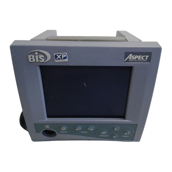
Page 9: Figure 1-1 The A-2000 Bis Monitoring System
SECTION I INTRODUCTION Figure 1-1 The A-2000 BIS Monitoring System - 1-4 -... -
Page 10: Figure 1-2 Rear View Of Monitor
SECTION I INTRODUCTION Clamp Shoe Fuse Holder Potential Equalization Serial Terminal Port Figure 1-2 Rear View of Monitor - 1-5 -... - Page 11 SECTION I INTRODUCTION - 1-6 -...
-
Page 12: Safety Precautions
SECTION II SAFETY PRECAUTIONS SECTION II SAFETY PRECAUTIONS INTRODUCTION Caution: Carefully read the entire A-2000 Operating Manual before using the monitor in a clinical setting. 2.1.1 WARNINGS, CAUTIONS, AND NOTES The terms warning, caution, and note have specific meanings in this manual. •... - Page 13 SECTION II SAFETY PRECAUTIONS UNIVERSAL PRECAUTIONS SHALL BE OBSERVED TO PREVENT CONTACT WITH BLOOD OR OTHER POTENTIALLY INFECTIOUS MATERIALS. PLACE CONTAMINATED MATERIALS IN REGULATED WASTE CONTAINER. DO NOT MIX DISINFECTING SOLUTIONS (e.g. BLEACH AND AMMONIA) AS HAZARDOUS GASES MAY RESULT. ELECTRICAL SHOCK HAZARD: DO NOT REMOVE MONITOR COVERS DURING OPERATION OR WHILE POWER IS CONNECTED TO MONITOR.
-
Page 14: Cautions
The A-2000 contains an internal Nickel-Metal-Hydride battery. The battery must be removed by a qualified service technician and disposed of or recycled in accordance with the national laws of the country. Contact Aspect Medical Systems, Inc. or the local distributor for a replacement battery. - Page 15 Replace battery only with same type of approved battery. Use of non-approved battery may result in incorrect operation or damage to the monitor. A-2000 is a trademark and Bispectral Index, BIS and Zipprep are registered trademarks of Aspect Medical Systems, Inc. - 2-4 -...
-
Page 16: Key To Symbols
SECTION II SAFETY PRECAUTIONS KEY TO SYMBOLS ON (power; connection to the mains) OFF (power; disconnection from the mains) Audible Alarm Silenced Operating on Battery Type BF Equipment Attention, Consult Accompanying Documents Attention, J1 RS-232 Serial Port, Consult Accompanying Documents Attention, J2 Printer Port, Consult Accompanying Documents - 2-5 -... - Page 17 SECTION II SAFETY PRECAUTIONS Fuse, Replace only with same Type and Rating Equipotential Alternating Current Dangerous Voltage Protective Earth (ground) Storage Temperature Limits - 2-6 -...
-
Page 18: Principles Of Operation
SECTION III PRINCIPLES OF OPERATION SECTION III PRINCIPLES OF OPERATION The A-2000 BIS Monitoring System consists of: • The BIS monitor with built-in battery backup and detachable power cord • The Digital Signal Converter (DSC) • Aspect’s BIS Sensor Patient Interface Cable (PIC) and BIS Sensor This section describes the architecture of the A-2000 monitor and DSC and how their constituent parts interact. -
Page 19: Figure 3-1 The A-2000 System Block Diagram
SECTION III PRINCIPLES OF OPERATION Figure 3-1 The A-2000 System Block Diagram - 3-2 -... -
Page 20: Figure 3-2 The A-2000 Signal Flow Diagram
SECTION III PRINCIPLES OF OPERATION Figure 3-2 The A-2000 Signal Flow Diagram - 3-3 -... - Page 21 SECTION III PRINCIPLES OF OPERATION 3.1.1.1 The DSC’s Preamplifier Board The preamplifier board contains the input protection circuits, montage mode switches, differential amplifiers, filter and gain amplifiers, impedance test circuits, self test circuits, and parts of the sensor ID circuit. 3.1.1.2 DSC Signal Conditioning The input protection circuits are designed to protect the inputs from destruction by electric shock from sources such as electrostatic discharge (ESD) or defibrillation.
- Page 22 SECTION III PRINCIPLES OF OPERATION 3.1.1.4 The DSC Communications Board The communications board contains the analog to digital (A/D) converter for each channel, the monitor interface, the sensor interface and the power supply circuits. A crystal controlled DSC master clock is on this board. This clock is the system’s BIS processing clock. A/D Conversion (Patented technology) The communications board contains sigma-delta modulators for the two channels.
-
Page 23: Figure 3-3 The Digital Signal Converter (Dsc)
SECTION III PRINCIPLES OF OPERATION Monitor DSC - 2 Interface Cable DSC pigtail Patient Interface Cable (PIC) Figure 3-3 The Digital Signal Converter (DSC) - 3-6 -... -
Page 24: The A-2000 Monitor
SECTION III PRINCIPLES OF OPERATION 3.1.2 The A-2000 Monitor The A-2000 monitor contains the circuits for digitally processing the EEG data, computing the processed parameters, and displaying the waveforms and processed parameters. The circuits for acquiring the EEG signal and digitizing them reside in the digital signal converter (DSC). -
Page 25: A-2000 Printer
SECTION III PRINCIPLES OF OPERATION 3.1.2.5 The Interconnect Board The A-2000 monitor is designed with a minimum of internal cabling. The Interconnect board provides the physical mounting and electrical connections for the major subassemblies of the A-2000. It has mounted to it the power input module (connector for the AC power cord and associated fuses), the equipotential stud, the power switch, and connectors for the printer (external), the serial port (external) and the various internal connectors for the Main PCB, Switch pad, battery, and fan. -
Page 26: Preparation For Use And Installation
SECTION IV PREPARATION FOR USE AND INSTALLATION SECTION IV PREPARATION FOR USE AND INSTALLATION INTRODUCTION This section provides installation instructions for the Aspect A-2000 BIS Monitor, Digital Signal Converter and accessories including: • Site preparation • Instrument connections • Installation and verification procedure •... -
Page 27: Power Requirements And System Grounding
SECTION IV PREPARATION FOR USE AND INSTALLATION 4.1.3 Power Requirements and System Grounding The A-2000 BIS Monitor requires a power source of 100-240 VAC, 50-60Hz. Current consumption is 1 ampere maximum (including printer load). To protect operating personnel and patients, the monitor must be properly grounded. Accordingly, the monitor is equipped with a hospital grade line cord. -
Page 28: Instrument Connections
SECTION IV PREPARATION FOR USE AND INSTALLATION INSTRUMENT CONNECTIONS Detailed connection instructions are provided in the A-2000 Operating Manual, Section III. 4.2.1 Digital Signal Converter Connections The long flexible cable from the A-2000 Digital Signal Converter connects to the electrically isolated digital signal converter connector on the front panel of the monitor. Once connected, the DSC need not be disconnected again. -
Page 29: Installation And Verification Procedure
SECTION IV PREPARATION FOR USE AND INSTALLATION INSTALLATION AND VERIFICATION PROCEDURE 1. Open packages and inspect for all components: • Monitor with power cable • DSC (Digital Signal Converter) • PIC (Patient interface cable) You will also need a BIS Sensor or Sensor Simulator. 2. -
Page 30: Preventive Maintenance, Care And Cleaning
SECTION V PREVENTIVE MAINTENANCE, CARE AND CLEANING SECTION V PREVENTIVE MAINTENANCE, CARE AND CLEANING INTRODUCTION This section describes: • Care and cleaning procedures • Routine maintenance CARE AND CLEANING WARNING: UNIVERSAL PRECAUTIONS SHALL BE OBSERVED TO PREVENT CONTACT WITH BLOOD OR OTHER POTENTIALLY INFECTIOUS MATERIALS. -
Page 31: Routine Maintenance
SECTION V PREVENTIVE MAINTENANCE, CARE AND CLEANING ROUTINE MAINTENANCE The A-2000 monitor is designed so that no periodic adjustment or calibration is required. 5.2.1 Checking the Battery The battery must be tested periodically to verify that the A-2000 will continue to operate during power outages. - Page 32 SECTION V PREVENTIVE MAINTENANCE, CARE AND CLEANING WARNING: ELECTRICAL SHOCK HAZARD: THE MANUFACTURER’S INSPECTION OF THIS APPARATUS VERIFIED THAT THE GROUND LEAKAGE CURRENT AND THE PATIENT SAFETY CURRENT WERE LESS THAN THE SPECIFIED LIMITS ESTABLISHED BY THE APPLICABLE SAFETY STANDARDS. AS A MATTER OF SAFE PRACTICE, THE INSTITUTION SHOULD CONDUCT PERIODIC TESTS TO VERIFY THESE CURRENTS.
-
Page 33: Monitor System Checkout Procedure
SECTION V PREVENTIVE MAINTENANCE, CARE AND CLEANING 5.2.3 Monitor System Checkout Procedure The following test procedure should be performed periodically to ensure that the A-2000 is functioning properly. 1. Connect power cable to monitor, plug power connector into appropriate wall outlet. 2. -
Page 34: Dsc Checkout Procedure
SECTION V PREVENTIVE MAINTENANCE, CARE AND CLEANING 5.2.4 DSC Checkout Procedure Periodically the DSC and associated cables and connectors should be inspected for physical damage. 1. Inspect the DSC case to ensure the plastic is not cracked or broken. 2. Inspect the gasket seal around the perimeter of the DSC to verify the physical integrity of the seal. - Page 35 SECTION V PREVENTIVE MAINTENANCE, CARE AND CLEANING - 5-6 -...
-
Page 36: Diagnostics And Troubleshooting
SECTION VI DIAGNOSTICS AND TROUBLESHOOTING SECTION VI DIAGNOSTICS AND TROUBLESHOOTING INTRODUCTION This section explains: • General troubleshooting • The A-2000 power-up, automatic and manual diagnostic procedures • Failure messages, causes, and corrective actions • Diagnostic codes and their meanings GENERAL TROUBLESHOOTING Using Table 6.1, the technician can troubleshoot the A-2000 monitor by matching a symptom to the list of probable causes and recommended corrective procedures. - Page 37 SECTION VI DIAGNOSTICS AND TROUBLESHOOTING Table 6.1 CONTINUED Symptoms: Causes: Corrective Procedures: No speaker sound Alarms silenced Enable alarms Main board defective Replace main board Keypad inoperative Cable disconnected or Reconnect or replace defective cables Keypad defective Replace keypad Main board defective Replace main board All keys inoperative Main board defective...
- Page 38 SECTION VI DIAGNOSTICS AND TROUBLESHOOTING Table 6.1 CONTINUED Symptoms: Causes: Corrective Procedures: DSC overcurrent error DSC cable to monitor is Replace DSC message defective DSC is defective Replace DSC Main board defective Replace main board Noisy EEG Interference from other Initiate DSC self-test equipment (e.g.
-
Page 39: The A-2000 Diagnostic Procedures
SECTION VI DIAGNOSTICS AND TROUBLESHOOTING THE A-2000 DIAGNOSTIC PROCEDURES The A-2000 has three built-in diagnostic procedures: • Power-Up • Automatic • Manual These procedures check the A-2000 unit’s operability and report software and hardware malfunctions. The power-up diagnostics run automatically each time you turn on the A-2000 unit. These procedures check the software (FLASH), system memory, speaker, display, serial ports, timer/counters, FPGA, BIS Engine, real-time clock, Data Memory and Setup Memory. - Page 40 SECTION VI DIAGNOSTICS AND TROUBLESHOOTING The second screen contains the following information: BIS Monitor Model A-2000 System Rev. x.xx Host Rev....…..x.xx Printer Port....…..OK Diagnostic Port....OK FPGA Rev....…..x.xx FPGA ......…….OK BIS Engine Rev.....x.xx BIS Engine ....….OK Real-Time Clock ....OK Data Memory ....
- Page 41 SECTION VI DIAGNOSTICS AND TROUBLESHOOTING MESSAGES, CAUSES AND CORRECTIVE ACTIONS The power-up diagnostics identify a number of problems involving the A-2000’s software and hardware. Table 6.3 shows the messages associated with these diagnostics as well as the cause of the failure and the corrective action to take. Messages are arranged and listed in the following categories: RAM, program memory, I/O devices, BIS Engine, real- time clock, data memory, and setup memory.
- Page 42 SECTION VI DIAGNOSTICS AND TROUBLESHOOTING Table 6.3 Power-Up Failure Messages, Causes and Corrective Actions (CONTINUED) Failure Messages: Causes: Corrective Actions: BIS Engine Initialization: Problem with BIS Engine on Replace main board. Engine....FAILED main board. Real-Time Clock Checks: Real-Time Real-time clock failed RAM Replace main board.
-
Page 43: Automatic Diagnostics
SECTION VI DIAGNOSTICS AND TROUBLESHOOTING 6.2.2 Automatic Diagnostics The A-2000 monitor contains a series of diagnostics that run constantly in the background checking for problem conditions. When a problem condition occurs, the monitor signals with alarm tones (two beeps, sounds like “Uh-oh”) and a status message that appears in the Message Region of the display. - Page 44 SECTION VI DIAGNOSTICS AND TROUBLESHOOTING Table 6.4 Automatic Diagnostic Error Messages, Causes and Corrective Actions (CONTINUED) Failure Messages: Causes: Corrective Actions: Sensor 1. Defective Sensor. 1. Replace the Sensor. Illegal Sensor Type 2. Defective PIC. 2. Replace the PIC. 3. Defective DSC. 3.
- Page 45 SECTION VI DIAGNOSTICS AND TROUBLESHOOTING Table 6.4 Automatic Diagnostic Error Messages, Causes and Corrective Actions (CONTINUED) Failure Messages: Causes: Corrective Actions: EEG Signal With 2-channel montage, 1. Re-prep the Sensor. Left Side SQI Bad left side signal quality is 2. Check impedances. bad.
- Page 46 SECTION VI DIAGNOSTICS AND TROUBLESHOOTING Table 6.4 Automatic Diagnostic Error Messages, Causes and Corrective Actions (CONTINUED) Failure Messages: Causes: Corrective Actions: Battery The AC power has been Restore the AC power. Operating On Battery lost and the monitor is Backup running on the battery.
- Page 47 SECTION VI DIAGNOSTICS AND TROUBLESHOOTING Table 6.4 Automatic Diagnostic Error Messages, Causes and Corrective Actions (CONTINUED) Failure Messages: Causes: Corrective Actions: Printer Printer is out of paper. Replace the paper. Printer Out of Paper 1. Printer is off-line. 1. Put printer on-line. Printer Error 2.
-
Page 48: Manual Diagnostics
SECTION VI DIAGNOSTICS AND TROUBLESHOOTING 6.2.3 Manual Diagnostics Diagnostic tests may be initiated by selecting them from the Diagnostic Menu. 1. Press the [MENU/EXIT] key from the Main Screen to access the Setup menu. 2. Highlight Advanced Setup using the [▲] or [▼] key, then press [SELECT]. 3. - Page 49 SECTION VI DIAGNOSTICS AND TROUBLESHOOTING 6.2.3.2 Display Self Test To initiate a test of the screen display, highlight Display Self Test and press [SELECT]. The following screen is displayed: Press SELECT to start test. Press MENU/EXIT to end test. When [SELECT] is pressed, the display will start to cycle through 3 test screens: a) All pixels on.
- Page 50 SECTION VI DIAGNOSTICS AND TROUBLESHOOTING 6.2.3.3 Using the Diagnostic Codes If you are experiencing problems with the A-2000 system, you may wish to turn the Diagnostic Codes ON so that numerical diagnostic values will be displayed in the message region of the screen. This feature is intended for qualified service personnel. Refer to Table 6.5 for a description of the codes.
- Page 51 SECTION VI DIAGNOSTICS AND TROUBLESHOOTING Table 6.5 Diagnostic Codes and their Meanings (CONTINUED) Display Code Description Code Meaning 00400000 DSC Overcurrent DSC is drawing too much current. The DSC is automatically turned off by the hardware. This bit is valid 100 ms after the DSC is turned on.
- Page 52 SECTION VI DIAGNOSTICS AND TROUBLESHOOTING 6.2.3.4 Impedance Checking The A-2000 continually checks impedance levels during a procedure by generating a 128 Hz test signal. Occasionally this signal may interfere with other equipment. If this becomes a problem, you may turn off the continuous impedance checking in the Diagnostic Menu.
- Page 53 SECTION VI DIAGNOSTICS AND TROUBLESHOOTING - 6-18 -...
-
Page 54: Disassembling And Reassembling The A-2000
SECTION VII DISASSEMBLING AND REASSEMBLING THE A-2000™ SECTION VII DISASSEMBLING AND REASSEMBLING THE A-2000 INTRODUCTION This section provides instructions for removing and replacing parts within the A-2000 monitor unit. Note: The Digital Signal Converter (DSC) is sealed; there are no serviceable parts inside. -
Page 55: Required Tools And Supplies
SECTION VII DISASSEMBLING AND REASSEMBLING THE A-2000™ REQUIRED TOOLS AND SUPPLIES Table 7.1 Tools and Supplies to Assemble/ Disassemble the A-2000 Monitor Tool or Supply: Required for: #1 phillips screwdriver Removing the monitor cover screws, bezel #2 phillips screwdriver screws, the electro-luminescent display panel, main board assembly, power supply, battery, and fan 7/16”... -
Page 56: The Monitor Case
SECTION VII DISASSEMBLING AND REASSEMBLING THE A-2000™ THE MONITOR CASE 7.2.1 Opening the Monitor Case WARNING: DUE TO THE BATTERY OPERATION POSSIBLE WITH NO AC CONNECTED, EXTREME CARE MUST BE USED WHEN DISASSEMBLING AND ASSEMBLING THE A-2000 MONITOR. WITH AC DISCONNECTED AND BATTERY POWER ON, HIGH VOLTAGE IS PRESENT ON THE E/L DISPLAY AND POWER SUPPLY PCB. - Page 57 SECTION VII DISASSEMBLING AND REASSEMBLING THE A-2000™ 6. Using Loctite 425, install 2 rubber feet and screws into the bottom of the monitor. Do not tighten. Caution: VERY IMPORTANT! Use only the Loctite number specified. Using the incorrect Loctite will damage plastic components. 7.
-
Page 58: Figure 7-1 Opening The Monitor Case
SECTION VII DISASSEMBLING AND REASSEMBLING THE A-2000™ Figure 7-1 Opening the Monitor Case Tape Figure 7-2 The E/L Display Cable - 7-5 -... -
Page 59: Figure 7-3 The Keypad Cable Tension Flange
SECTION VII DISASSEMBLING AND REASSEMBLING THE A-2000™ Flange Figure 7-3 The Keypad Cable Tension Flange - 7-6 -... -
Page 60: The Electro/Luminescent Display
SECTION VII DISASSEMBLING AND REASSEMBLING THE A-2000™ THE ELECTRO/LUMINESCENT DISPLAY 7.3.1 Removing the E/L Display Board 1. With bezel assembly dismounted from case (see section 7.2.1), remove the four mounting screws. (See Figure 7-4). 2. Pull the board free, leaving the gasket in place. 7.3.2 Reattaching the E/L Display Board 1. -
Page 61: Figure 7-4 The Four Mounting Screws
SECTION VII DISASSEMBLING AND REASSEMBLING THE A-2000™ Figure 7-4 The Four Mounting Screws - 7-8 -... -
Page 62: The Front Panel Switch Set
SECTION VII DISASSEMBLING AND REASSEMBLING THE A-2000™ THE FRONT PANEL SWITCH SET The switch set is not serviceable and should not be removed unless a new one is to be installed. Removing the switch set will destroy it. 7.4.1 Removing the Switch Set 1. -
Page 63: Figure 7-5 The Cable Access Port
SECTION VII DISASSEMBLING AND REASSEMBLING THE A-2000™ EMI strip Figure 7-5 The Cable Access Port Figure 7-6 Remove the covering on the back of the new switch set - 7-10 -... -
Page 64: The Printed Circuit Board Assembly
SECTION VII DISASSEMBLING AND REASSEMBLING THE A-2000™ THE PRINTED CIRCUIT BOARD ASSEMBLY The Interconnect PCB and connected assemblies must be removed to gain access to the Main PCB, fan, battery, power supply, or rear case shell. 7.5.1 Removing the Printed Circuit Board assembly 1. - Page 65 SECTION VII DISASSEMBLING AND REASSEMBLING THE A-2000™ 6. Loosen L bracket screw (Fig. 7-10). Be sure to check that the alignment of bottom screws is adequate, then install rubber foot, flat head steel (in center position), and flat head nylon screw (right side). Tighten nylon screw first. Do not over-tighten nylon screw.
-
Page 66: Figure 7-7 Place Rear Case Assembly Face Down On A Scratch Free Work Surface
SECTION VII DISASSEMBLING AND REASSEMBLING THE A-2000™ Equipotential Stud Flat screw Nylon screw Figure 7-7 Place rear case assembly face down on a scratch free work surface Figure 7-8 Fan Cable - 7-13 -... -
Page 67: The Main Pcb
SECTION VII DISASSEMBLING AND REASSEMBLING THE A-2000™ THE MAIN PCB 7.6.1 Removing the Main PCB 1. Open the monitor case as described in Section 7.2.1. 2. Remove the Printed Circuit Board Assembly as described in Section 7.5.1. 3. To separate Main PCB from Interconnect assembly, release standoff tab by squeezing with needle-nose pliers, while gently separating at standoff. -
Page 68: Figure 7-9 Release Standoff Tab By Squeezing With Needle-Nose Pliers
SECTION VII DISASSEMBLING AND REASSEMBLING THE A-2000™ Figure 7-9 Release standoff tab by squeezing with needle-nose pliers L bracket Figure 7-10 The L bracket - 7-15 -... -
Page 69: Figure 7-11 Gently Pull And Flex To Separate Pcbs
SECTION VII DISASSEMBLING AND REASSEMBLING THE A-2000™ Interconnect Power Supply Main Figure 7-11 Gently pull and flex to separate PCBs Interconnect PCB Notch Interconnect PCB Main PCB socket pins Figure 7-12 Line up Interconnect PCB pins to Main PCB socket - 7-16 -... -
Page 70: Figure 7-13 Align Standoffs And Push In Until Standoff Tabs Snap Into Place
SECTION VII DISASSEMBLING AND REASSEMBLING THE A-2000™ Figure 7-13 Align standoffs and push in until standoff tabs snap into place Figure 7-14 Install L bracket by holding long side; short side connects to Main - 7-17 -... -
Page 71: Figure 7-15 The L Bracket Installed
SECTION VII DISASSEMBLING AND REASSEMBLING THE A-2000™ L bracket Figure 7-15 The L Bracket Installed - 7-18 -... -
Page 72: The Power Supply Pcb
SECTION VII DISASSEMBLING AND REASSEMBLING THE A-2000™ THE POWER SUPPLY PCB 7.7.1 Removing the Power Supply PCB 1. Open the monitor case as described in Section 7.2.1. 2. Remove the Interconnect PCB as described in Section 7.5.1. 3. Disconnect battery cable from PCB by depressing securing tab and lifting connector from J300 jack. -
Page 73: Figure 7-16 Gently Flex And Pull Power Supply Pcb Free Of Pins
SECTION VII DISASSEMBLING AND REASSEMBLING THE A-2000™ Figure 7-16 Gently flex and pull Power Supply PCB free of pins Figure 7-17 Remove four screws on rear of Power Supply PCB - 7-20 -... -
Page 74: Figure 7-18 Remove Shield From Rear Of Power Supply Pcb
SECTION VII DISASSEMBLING AND REASSEMBLING THE A-2000™ Figure 7-18 Remove shield from rear of Power Supply PCB - 7-21 -... -
Page 75: The Battery
ELECTRICAL SHOCK HAZARD. Caution: Used batteries must be recycled or disposed of properly. Contact Aspect Medical Systems or your local distributor for a replacement battery and instructions for returning the defective battery for proper recycling/disposal. 8. Open the monitor case as described in Section 7.2.1. -
Page 76: Figure 7-19 Battery And Cable
SECTION VII DISASSEMBLING AND REASSEMBLING THE A-2000™ Tie Wraps J 300 Figure 7-19 Battery and cable - 7-23 -... -
Page 77: The Fan
SECTION VII DISASSEMBLING AND REASSEMBLING THE A-2000™ THE FAN 7.9.1 Removing the Fan WARNING: DUE TO THE BATTERY OPERATION POSSIBLE WITH NO AC CONNECTED, EXTREME CARE MUST BE USED WHEN DISASSEMBLING AND ASSEMBLING THE A-2000 MONITOR. WITH AC DISCONNECTED AND BATTERY POWER ON, HIGH VOLTAGE IS PRESENT ON THE E/L DISPLAY AND POWER SUPPLY PCB. -
Page 78: Figure 7-20 Fan Wiring Orientation And Clamp Shoe Screws
SECTION VII DISASSEMBLING AND REASSEMBLING THE A-2000™ Wiring Fan Mounting Screws (4) Clamp Shoe Screws Figure 7-20 Fan wiring orientation and Clamp Shoe screws Fan Mounting Screws (2) Rubber Conductive Bumper Copper Tape Figure 7-21 Updated System with 2 Fan Mounting screws and Copper Tape - 7-25 -... -
Page 79: The Clamp Shoe Assembly
SECTION VII DISASSEMBLING AND REASSEMBLING THE A-2000™ 7.10 THE CLAMP SHOE ASSEMBLY 7.10.1 Removing the Clamp Shoe Assembly 1. Open the monitor case as described in Section 7.2.1. 2. Remove the Interconnect PCB as described in Section 7.5.1. 3. Remove three screws securing shoe clamp assembly. (See Figure 7-20). 7.10.2 Installing the Clamp Shoe Assembly 1. -
Page 80: Fuse Replacement
SECTION VII DISASSEMBLING AND REASSEMBLING THE A-2000™ 7.11 FUSE REPLACEMENT The A-2000 contains two inline fuses (1.25A, 250V, 5x20mm Aspect P/N 430-0006) within the AC power input module located at the rear of the monitor. In the unlikely event that a fuse needs to be replaced, one can access these fuses as follows: 1. -
Page 81: Figure 7-22 Releasing The Plastic Locking Tabs Of The Fuse Holder
SECTION VII DISASSEMBLING AND REASSEMBLING THE A-2000™ Figure 7-22 Releasing the plastic locking tabs of the fuse holder Figure 7-23 Re-installing the fuse holder - 7-28 -... -
Page 82: A-2000 Specifications
SECTION VIII A-2000™ SPECIFICATIONS SECTION VIII A-2000 SPECIFICATIONS INTRODUCTION This section lists specifications for the Aspect A-2000 BIS Monitor. GENERAL SPECIFICATIONS: • Product Description: BIS (Bispectral Index) monitor for display up to 2 channels of processed data and real-time EEG waveforms •... - Page 83 SECTION VIII A-2000™ SPECIFICATIONS EEG Specifications: • Epoch Duration: 2 seconds • Artifact Rejection: Automatic 25 µV/div (+/- 1 mV Full Scale) • EEG Scales: • EEG Sweep Speeds: 25 mm/sec • Computed Parameters: Bispectral Index, 95% Spectral Edge Frequency, Suppression Ratio, EMG and Signal Quality Index •...
-
Page 84: Type Of Protection Against Electric Shock Of The System
SECTION VIII A-2000™ SPECIFICATIONS 8.1.1 Type of Protection against Electric Shock of the System: Class 1: Equipment in which protection against electric shock does not rely on basic insulation only, but which includes an additional safety precaution. Means are provided for the connection of the equipment to the protective earth conductor in the fixed wiring of the installation in such a way that accessible metal parts cannot become live in the event of a failure of the basic insulation. -
Page 85: Digital Signal Converter (Dsc) Connector
SECTION VIII A-2000™ SPECIFICATIONS Digital Signal Converter (DSC) Connector LEMO – 5 female - 8-4 -... -
Page 86: Warranty
SECTION VIII A-2000™ SPECIFICATIONS WARRANTY Aspect warrants to the initial Purchaser that the A-2000 BIS monitor and the Digital Signal Converter (“Warranted Product”) will be free from defects in workmanship or materials, when given normal, proper, and intended usage for a period of one year (“Warranty Period”) from the date of its initial shipment to Purchaser. - Page 87 SECTION VIII A-2000™ SPECIFICATIONS LOSS OF USE OF ANY PRODUCT. EXCEPT AS SET FORTH HEREIN, ALL PRODUCTS ARE SUPPLIED “AS IS” WITHOUT WARRANTY OF ANY KIND, EITHER EXPRESS OR IMPLIED. - 8-6 -...
-
Page 88: Appendices
SECTION IX APPENDICES SECTION IX APPENDICES APPENDIX I - A-2000 PARTS LIST This section lists the names of the A-2000 monitor’s assembly parts and part numbers. Use these numbers when ordering an assembly replacement. Part Name Description Number 070-0015 A-2000 Operating Manual 075-0002 A-2000 Service Manual 140-0017... -
Page 89: Appendix Ii - Sensor Simulator - Instructions For Use
SECTION IX APPENDICES APPENDIX II - SENSOR SIMULATOR - INSTRUCTIONS FOR USE Description of device: The sensor simulator is a service tool that allows for the verification of proper impedance values being detected by the BIS monitors during the “Check electrodes”. This test is part of the initial test that each monitor performs. The simulator also allows for safety testing of BIS monitors in the field by allowing connection of the test equipment to the monitor via the patient interface cable. - Page 90 Proceed to test instrument for Leakage current as per established facility protocols and procedure for safety testing of medical devices. For technical assistance contact: Aspect Medical Systems, Inc. Technical Service 2 Vision Drive Natick, MA 01760...
- Page 92 (800) 442-7688 … press (6) Technical Service: (800) 442-2051 Email: bis_info@aspectms.com Web: www.aspectms.com Aspect Medical Systems International B.V. Haagse Schouwweg 8 2332 KG Leiden The Netherlands Main Business Phone: +31 071 572 5935 Main Business Fax: +31 071 572 5936...
Need help?
Do you have a question about the BISPECTRAL INDEX A-2000 and is the answer not in the manual?
Questions and answers