Sign In
Upload
Manuals
Brands
Aspect Medical Systems Manuals
Medical Equipment
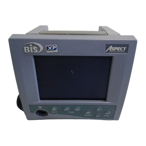
BISPECTRAL INDEX A-2000
Aspect Medical Systems BISPECTRAL INDEX A-2000 Manuals
Manuals and User Guides for Aspect Medical Systems BISPECTRAL INDEX A-2000. We have
1
Aspect Medical Systems BISPECTRAL INDEX A-2000 manual available for free PDF download: Service Manual
Aspect Medical Systems BISPECTRAL INDEX A-2000 Service Manual (92 pages)
MONITORING SYSTEM
Brand:
Aspect Medical Systems
| Category:
Medical Equipment
| Size: 4 MB
Table of Contents
Table of Contents
2
Introduction
6
About this Manual
6
Introducing the A-2000 bis Monitoring System
7
Principal Components
7
How the A-2000 Works
8
Instrument Identification
8
A-2000 Monitor
8
A-2000 Digital Signal Converter
8
Software Revision Numbers
8
Proprietary Information and Devices
8
Figure 1-1 the A-2000 bis Monitoring System
9
Figure 1-2 Rear View of Monitor
10
Safety Precautions
12
Warnings, Cautions, and Notes
12
Warnings
12
Cautions
14
Key to Symbols
16
Principles of Operation
18
System Architecture
18
The Digital Signal Converter (DSC)
18
Figure 3-1 the A-2000 System Block Diagram
19
Figure 3-2 the A-2000 Signal Flow Diagram
20
Figure 3-3 the Digital Signal Converter (DSC)
23
The A-2000 Monitor
24
A-2000 Printer
25
Preparation for Use and Installation
26
Environment
26
Shipping and Storage Environment
26
Operating Environment
26
Power Requirements and System Grounding
27
Site Preparation
27
Instrument Connections
28
Digital Signal Converter Connections
28
Power Cord Connections
28
Printer Connector
28
Installation and Verification Procedure
29
Repackaging for Shipping and Storage
29
Preventive Maintenance, Care and Cleaning
30
Care and Cleaning
30
Cleaning the Monitor and Digital Signal Converter
30
Disinfecting the Monitor and Digital Signal Converter
30
Cleaning the Monitor Display
30
Routine Maintenance
31
Checking the Battery
31
Checking Leakage Current
31
Monitor System Checkout Procedure
33
DSC Checkout Procedure
34
Patient Interface Cable (PIC) Checkout Procedure
34
Diagnostics and Troubleshooting
36
General Troubleshooting
36
The A-2000 Diagnostic Procedures
39
Power-Up Diagnostics
39
Automatic Diagnostics
43
Manual Diagnostics
48
Disassembling and Reassembling the A-2000
54
Required Tools and Supplies
55
The Monitor Case
56
Opening the Monitor Case
56
Closing the Monitor Case
56
Figure 7-1 Opening the Monitor Case
58
Figure 7-2 the E/L Display Cable
58
Figure 7-3 the Keypad Cable Tension Flange
59
The Electro/Luminescent Display
60
Removing the E/L Display Board
60
Reattaching the E/L Display Board
60
Figure 7-4 the Four Mounting Screws
61
The Front Panel Switch Set
62
Removing the Switch Set
62
Installing the New Switch Set
62
Figure 7-5 the Cable Access Port
63
Figure 7-6 Remove the Covering on the Back of the New Switch Set
63
The Printed Circuit Board Assembly
64
Removing the Printed Circuit Board Assembly
64
Installing the Printed Circuit Board Assembly
64
Figure 7-7 Place Rear Case Assembly Face down on a Scratch Free Work Surface
66
Figure 7-8 Fan Cable
66
The Main Pcb
67
Removing the Main PCB
67
Installing the Main PCB
67
Figure 7-9 Release Standoff Tab by Squeezing with Needle-Nose Pliers
68
Figure 7-10 the L Bracket
68
Figure 7-11 Gently Pull and Flex to Separate Pcbs
69
Figure 7-12 Line up Interconnect PCB Pins to Main PCB Socket
69
Figure 7-13 Align Standoffs and Push in until Standoff Tabs Snap into Place
70
Figure 7-14 Install L Bracket by Holding Long Side; Short Side Connects to Main PCB
70
Figure 7-15 the L Bracket Installed
71
The Power Supply Pcb
72
Removing the Power Supply PCB
72
Installing the Power Supply PCB
72
Figure 7-16 Gently Flex and Pull Power Supply PCB Free of Pins
73
Figure 7-17 Remove Four Screws on Rear of Power Supply PCB
73
Figure 7-18 Remove Shield from Rear of Power Supply PCB
74
The Battery
75
Removing the Battery
75
Installing the Battery
75
Figure 7-19 Battery and Cable
76
The Fan
77
Removing the Fan
77
Installing the Fan
77
Figure 7-20 Fan Wiring Orientation and Clamp Shoe Screws
78
Figure 7-21 Updated System with 2 Fan Mounting Screws and Copper Tape
78
The Clamp Shoe Assembly
79
Removing the Clamp Shoe Assembly
79
Installing the Clamp Shoe Assembly
79
Fuse Replacement
80
Figure 7-22 Releasing the Plastic Locking Tabs of the Fuse Holder
81
Figure 7-23 Re-Installing the Fuse Holder
81
A-2000 Specifications
82
General Specifications
82
Type of Protection against Electric Shock of the System
84
Degree of Protection against Electric Shock of the System
84
Degree of Protection against the Ingress of Water
84
Mode of Operation of the System
84
Classification
84
Options and Accessories
84
Digital Signal Converter (DSC) Connector
85
Warranty
86
Appendices
88
Appendix I - A-2000 Parts List
88
Appendix II - Sensor Simulator - Instructions for Use
89
Advertisement
Advertisement
Related Products
Aspect Medical Systems BIS VIEW
Aspect Medical Systems XP PLATFORM A-2000
Aspect Medical Systems Categories
Medical Equipment
More Aspect Medical Systems Manuals
Login
Sign In
OR
Sign in with Facebook
Sign in with Google
Upload manual
Upload from disk
Upload from URL