Table of Contents
Advertisement
Quick Links
Aspect Medical Systems
A-2000
BISPECTRAL INDEX
TM
(BIS
SERVICE INFORMATION
© Copyright, 2009, Aspect Medical Systems. All rights reserved. Copying or other reproduction
of this document is prohibited without prior written consent of Aspect Medical Systems.
Aspect Medical Systems, Inc.
One Upland Road
Norwood, MA
U.S.A.
(Tel) 617-559-7000
(Tel) 888-BIS INDE(X) (U.S. only)
(Fax) 617-559-7400
bis_info@aspectms.com
www.aspectmedical.com
TM
XP PLATFORM
) MONITORING SYSTEM
MANUAL
Rx Only
EC REP
Aspect Medical Systems International B.V.
Rijnzathe 7d2
3454 PV De Meern
The Netherlands
Tel: +31.30.662.9140
Fax: +31.30.662.9150
amsint@aspectms.com
TM
075-0014 1.04
Advertisement
Table of Contents
Troubleshooting

Related Manuals for Aspect Medical Systems XP PLATFORM A-2000


Summary of Contents for Aspect Medical Systems XP PLATFORM A-2000
- Page 1 ) MONITORING SYSTEM SERVICE INFORMATION MANUAL Rx Only © Copyright, 2009, Aspect Medical Systems. All rights reserved. Copying or other reproduction of this document is prohibited without prior written consent of Aspect Medical Systems. EC REP Aspect Medical Systems, Inc.
-
Page 3: Table Of Contents
TABLE OF CONTENTS 1 SAFETY PRECAUTIONS ..................1-1 1.1 WARNINGS......................1-1 1.2 CAUTIONS ......................1-3 1.3 KEY TO SYMBOLS ....................1-5 2 A-2000 SYSTEM OVERVIEW .................2-1 2.1 INTRODUCING THE A-2000 BIS MONITORING SYSTEM ........2-1 2.1.1 P ..................2-1 RINCIPAL OMPONENTS 2.1.2 H A-2000 W ..................2-2 ORKS 2.2 INSTRUMENT IDENTIFICATION................2-2 2.2.1 A-2000 M... - Page 4 4.3 INSTALLATION AND VERIFICATION PROCEDURE..........4-5 5 PREVENTIVE MAINTENANCE, CARE AND CLEANING ........5-1 5.1 CARE AND CLEANING ..................5-1 5.1.1 C ........5-1 LEANING THE ONITOR AND IGITAL IGNAL ONVERTER 5.1.2 D ......5-1 ISINFECTING THE ONITOR AND IGITAL IGNAL ONVERTER 5.1.3 C .................5-1 LEANING THE ONITOR ISPLAY...
- Page 5 9.1 SPARES AND ACCESSORIES LIST..............9-1 9.2 SENSOR SIMULATOR: P/N: 186-0137 FOR USE WITH DSC-XP: ....9-2 9.3 TEST SENSOR......................9-3 9.4 SAFETY TESTER CONNECTION WITH PIC............9-5 9.5 PLACEMENT OF PIC SECURING STRAP ON BIS MONITORING SYSTEM ..9-6 10 APPENDIX II ......................10-1 10.1 A-2000 SIGNAL FLOW DIAGRAM ..............10-1 10.2 A-2000 BLOCK DIAGRAM .................10-2 10.3 DSC WIRING DIAGRAM;...
- Page 6 TABLE OF FIGURES Figure 2-1 The A-2000 BIS Monitoring System ..................2-3 Figure 2-2 Rear View of Monitor ....................... 2-4 Figure 3-1 The A-2000 System Block Diagram..................3-2 Figure 3-2 The A-2000 Signal Flow Diagram ................... 3-3 Figure 4-1 Pole Clamp..........................4-3 Figure 7-1 Placement of PIC Securing Strap on BIS Monitoring System ..........
- Page 7 ABOUT THIS MANUAL _____________________________________________________________________________ ABOUT THIS MANUAL This manual contains information necessary for the customer to install, maintain, service, identify and prepare for use the Aspect Medical System BIS™ Monitoring System. Also included are directions to diagnose, troubleshoot, and repair the system. A spare parts and accessories list and system specifications are included.
- Page 8 ABOUT THIS MANUAL _____________________________________________________________________________...
-
Page 9: Safety Precautions
SECTION I SAFETY PRECAUTIONS ____________________________________________________________________________ SECTION I SAFETY PRECAUTIONS INTRODUCTION Caution: Carefully read the A-2000 BIS Monitoring System Operating Manual entirely before using the monitor in a clinical setting. WARNINGS, CAUTIONS, AND NOTES The terms warning, caution, and note have specific meanings in this manual. •... - Page 10 SECTION I SAFETY PRECAUTIONS ____________________________________________________________________________ IF THE INTEGRITY OF THE EXTERNAL PROTECTIVE EARTH GROUND IS IN DOUBT, THE A-2000 SHALL BE OPERATED FROM ITS INTERNAL BATTERY POWER SOURCE ONLY. FOR A-2000s USED OUTSIDE OF NORTH AMERICA: A HARMONIZED LINE CORD WITH CONDUCTORS HAVING A CROSS SECTIONAL AREA GREATER THAN 0.75 mm MUST BE USED.
-
Page 11: Cautions
SECTION I SAFETY PRECAUTIONS ____________________________________________________________________________ THE USE OF ACCESSORY EQUIPMENT NOT COMPLYING WITH THE EQUIVALENT SAFETY REQUIREMENTS OF THIS EQUIPMENT MAY LEAD TO A REDUCED LEVEL OF SAFETY OF THE RESULTING SYSTEM. CONSIDERATION RELATING TO THE CHOICE SHALL INCLUDE: • USE OF THE ACCESSORY IN THE PATIENT VICINITY •... - Page 12 Damage due to electrostatic discharge may result. A-2000 is a trademark of Aspect Medical Systems, Inc. Bispectral Index, BIS, the BIS logo, and Zipprep are trademarks of Aspect Medical Systems, Inc. and are registered in the U.S.A., E.U. and other countries.
-
Page 13: Key To Symbols
SECTION I SAFETY PRECAUTIONS ____________________________________________________________________________ 1.3 KEY TO SYMBOLS Caution: Consult Dangerous Voltage Accompanying Documents Attention, J1 RS-232 Serial Attention, J2 Printer Port, Consult Port, Consult Accompanying Accompanying Documents Documents Caution: Hot Surface Storage Temperature Limits Type BF Equipment Defibrillator- Type BF Equipment proof Alternating Current (A/C) - Page 14 *Contact Aspect Medical Systems International B.V. for a Return Materials Authorization (RMA) number. According to the WEEE Directive 2002/96/EC, all waste electrical and electronic equipment (EEE) should be disposed of and collected separately and treated according to the best available and environmentally friendly techniques.
-
Page 15: 2000 System Overview
A-2000 SYSTEM OVERVIEW 2.1 INTRODUCING THE A-2000 BIS MONITORING SYSTEM Aspect Medical Systems A-2000 BIS Monitoring System is intended to monitor the state of the brain by data acquisition of EEG signals in the intensive care unit, operating room, and for clinical research. -
Page 16: How The A-2000 Works
Software revision numbers are displayed in the Diagnostic Menu. 2.3 PROPRIETARY INFORMATION AND DEVICES Information and descriptions contained in this guide are the property of Aspect Medical Systems and may not be copied, reproduced or distributed without prior written permission. Portions of the... -
Page 17: Figure 2-1 The A-2000 Bis Monitoring System
SECTION II A-2000 SYSTEM OVERVIEW ____________________________________________________________________________ BIS Monitor Monitor Interface Cable DSC Pigtail Patient Interface Cable (PIC) Sensor Figure 2-1 The A-2000 BIS Monitoring System... -
Page 18: Figure 2-2 Rear View Of Monitor
SECTION II A-2000 SYSTEM OVERVIEW ____________________________________________________________________________ Clamp Shoe Fuse Holder Potential Equalization Serial Terminal Port AC Line Printer Connection Port Figure 2-2 Rear View of Monitor WARNING REPLACE FUSES ONLY WITH ONE OF THE FOLLOWING PARTS: Aspect P/N 430-0006, 1.25 Amps, 250V, 5x20mm Littelfuse 217 Series, 1.25 Amps, 250V, 5x20mm Wickmann 193 Series, 1.25 Amps, 250V, 5x20mm ALWAYS REPLACE BOTH FUSES TOGETHER, EVEN IF ONLY ONE HAS... -
Page 19: Principles Of Operation
SECTION III PRINCIPLES OF OPERATION _____________________________________________________________________________ SECTION III PRINCIPLES OF OPERATION INTRODUCTION This section includes: • How the A-2000 BIS Monitoring System works • The architecture of the A-2000 monitor and DSC • System Features 3.1 HOW THE A-2000 MONITORING SYSTEM WORKS Sensors placed on the patient's head transmit EEG signals to the Digital Signal Converter. -
Page 20: Figure 3-1 The A-2000 System Block Diagram
SECTION III PRINCIPLES OF OPERATION _____________________________________________________________________________ PREAMP Patient COMM BOARD Power Power Printer Earth Serial Connector Switch Port Stud Port INTERCONNECT BOARD J301 J200 POWER SUPPLY BOARD MAIN PROCESSOR BOARD J300 BATTERY KEYBOARD These connectors are internal to the board and DISPLAY are mated as shown. -
Page 21: Figure 3-2 The A-2000 Signal Flow Diagram
SECTION III PRINCIPLES OF OPERATION _____________________________________________________________________________ Input Filter SIGMA-DELTA Patient Protect Modulator Connection COMM Input Filter SIGMA-DELTA Protect Modulator Digital HOST Signal DISPLAY COMM Processor (DSP) Monitor Figure 3-2 The A-2000 Signal Flow Diagram After passing through input protection circuits in the DSC, the EEG signals are differentially amplified and filtered to remove DC and high frequency components. -
Page 22: The Digital Signal Converter (Dsc)
SECTION III PRINCIPLES OF OPERATION _____________________________________________________________________________ 3.2.1 The Digital Signal Converter (DSC) The DSC contains the inputs, amplifiers, and digitizers for two channels of EEG. It has a single point connection that connects via a Patient Interface Cable (PIC) to a BIS Sensor. The sensor and PIC contain circuits for identifying them to the monitor. - Page 23 SECTION III PRINCIPLES OF OPERATION _____________________________________________________________________________ 3.2.1.4 The DSC Communications Circuits The communications circuits contain the analog to digital (A/D) converter for each channel, the monitor interface, the sensor interface and the power supply circuits. A crystal controlled DSC master clock is on this board.
-
Page 24: The A-2000 Monitor
SECTION III PRINCIPLES OF OPERATION _____________________________________________________________________________ 3.2.2 The A-2000 Monitor The A-2000 monitor contains the circuits for digitally processing the EEG data, computing the processed parameters, and displaying the waveforms and processed parameters. The monitor also contains the circuits for powering the monitor, DSC, and companion printer. Printer function is not available on battery backup. -
Page 25: A-2000 Printer
SECTION III PRINCIPLES OF OPERATION _____________________________________________________________________________ 3.2.2.6 The Power Supply The power supply runs from AC power from 100-240 VAC, 50-60 Hz. It provides +5 V (at 6 A) and +12 V (at 0.72 A) outputs and charges the battery (6-cell NiMH) 7.2 V (nominal), 1800 mA. Signals are provided to the processor to indicate AC FAIL, RESET, and LOW BATTERY. -
Page 26: Data Memory
SECTION III PRINCIPLES OF OPERATION _____________________________________________________________________________ Impedance Check Electrode impedance is tested when the DSC and PIC are connected and is monitored continuously unless the user has turned impedance checking off in the Diagnostic Menu. Caution: Continuous impedance checking may need to be disabled if the 1 nanoampere 128 Hz impedance check signal interferes with other equipment, e.g., evoked potential monitors. -
Page 27: Printed Reports
SECTION III PRINCIPLES OF OPERATION _____________________________________________________________________________ WHEN CONNECTING EXTERNAL EQUIPMENT (e.g., DATA CAPTURE COMPUTER), THE SYSTEM LEAKAGE CURRENT MUST BE CHECKED AND MUST BE LESS THAN THE IEC601-1-1 LIMIT. NOTE: When software is upgraded, all previously recorded data and monitor configuration settings will be lost. - Page 28 SECTION III PRINCIPLES OF OPERATION _____________________________________________________________________________ 3-10...
-
Page 29: Preparation For Use And Installation
SECTION IV PREPARATION FOR USE AND INSTALLATION __________________________________________________________________________ SECTION IV PREPARATION FOR USE AND INSTALLATION INTRODUCTION This section provides an overview of installation information for service personnel working with the Aspect A-2000 BIS Monitor System. Please see the A-2000 BIS Monitoring System Operating Manual for full installation instructions. -
Page 30: Power Requirements And System Grounding
MUST BE USED. 4.1.4 Site Preparation: Mounting the Monitor Aspect Medical Systems, Inc. strongly recommends permanent mounting of the A-2000 monitor to the anesthesia machine to enhance safety and facilitate ease-of-use. Please contact your local representative or Aspect to discuss mounting options. -
Page 31: Instrument Connections
SECTION IV PREPARATION FOR USE AND INSTALLATION __________________________________________________________________________ Figure 4-1 Pole Clamp To remove the monitor, press tab on top of clamp shoe before sliding monitor up. The pole clamp may be locked onto the monitor so that the two do not get separated. To do this: 1. -
Page 32: Digital Signal Converter Connections
SECTION IV PREPARATION FOR USE AND INSTALLATION __________________________________________________________________________ 4.2.1 Digital Signal Converter Connections The long flexible cable from the A-2000 Digital Signal Converter connects to the electrically isolated digital signal converter connector on the front panel of the monitor. Once connected, the DSC need not be disconnected again. -
Page 33: Installation And Verification Procedure
SECTION IV PREPARATION FOR USE AND INSTALLATION __________________________________________________________________________ 4.3 INSTALLATION AND VERIFICATION PROCEDURE 1. Open packages and inspect for all components: • Monitor with power cable • DSC (Digital Signal Converter) • PIC (Patient interface cable) You will also need a BIS Sensor or Sensor Simulator. 2. - Page 34 SECTION IV PREPARATION FOR USE AND INSTALLATION __________________________________________________________________________...
-
Page 35: Preventive Maintenance, Care And Cleaning
SECTION V PREVENTIVE MAINTENANCE, CARE AND CLEANING _____________________________________________________________________________ SECTION V PREVENTIVE MAINTENANCE, CARE AND CLEANING INTRODUCTION This section describes: • Care and cleaning procedures • Preventive maintenance 5.1 CARE AND CLEANING WARNING: UNIVERSAL PRECAUTIONS SHALL BE OBSERVED TO PREVENT CONTACT WITH BLOOD OR OTHER POTENTIALLY INFECTIOUS MATERIALS. -
Page 36: Preventive Maintenance
The A-2000 contains an internal Nickel-Metal-Hydride battery. The battery must be removed by a qualified service technician and disposed of or recycled in accordance with the national laws of the country. Contact Aspect Medical Systems, Inc. or the local distributor for servicing of battery. WARNING: ELECTRICAL SHOCK HAZARD: DO NOT REMOVE MONITOR COVERS DURING OPERATION OR WHILE POWER IS CONNECTED TO MONITOR. -
Page 37: A-2000 Monitor System Checkout Procedure
SECTION V PREVENTIVE MAINTENANCE, CARE AND CLEANING _____________________________________________________________________________ WARNINGS: SHOCK HAZARD: DO NOT ATTEMPT TO DISCONNECT THE POWER CORD WITH WET HANDS. MAKE CERTAIN THAT YOUR HANDS ARE CLEAN AND DRY BEFORE TOUCHING THE POWER CORD. ELECTRICAL SHOCK HAZARD: THE MANUFACTURER’S INSPECTION OF THIS APPARATUS VERIFIED THAT THE GROUND LEAKAGE CURRENT AND THE PATIENT SAFETY CURRENT WERE LESS THAN THE SPECIFIED LIMITS ESTABLISHED BY THE APPLICABLE SAFETY STANDARDS. -
Page 38: Dsc Checkout Procedure
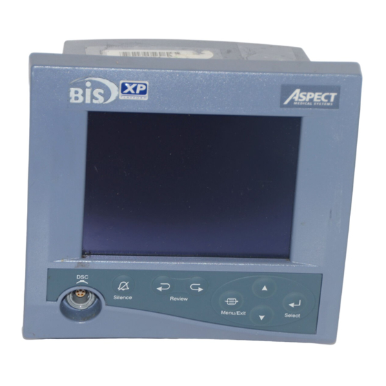
SECTION V PREVENTIVE MAINTENANCE, CARE AND CLEANING _____________________________________________________________________________ 8. Perform keyboard checkout: (a) Press SILENCE key Verify icon shows at BIS banner. (b) Press ARROW BACK key Verify REVIEW MODE screen displays. (c) Press MENU/EXIT key Verify REVIEW MODE screen exits. (d) Press ARROW AHEAD key Verify REVIEW MODE screen displays. -
Page 39: Physical Integrity Inspection
SECTION V PREVENTIVE MAINTENANCE, CARE AND CLEANING _____________________________________________________________________________ 4. A sensor check is initiated automatically when the sensor and PIC are connected to the DSC. (It may also be initiated by the user in the Setup Menu.) The impedance value for each electrode, in kilo ohms, appears on the screen along with its status: PASS - An electrode passes if the impedance for that electrode is less than 7.5 kilo ohms. - Page 40 SECTION V PREVENTIVE MAINTENANCE, CARE AND CLEANING _____________________________________________________________________________...
-
Page 41: Diagnostics And Troubleshooting
SECTION VI DIAGNOSTICS AND TROUBLESHOOTING ___________________________________________________________________________ SECTION VI DIAGNOSTICS AND TROUBLESHOOTING INTRODUCTION This section explains: • General troubleshooting using built in diagnostic tools • BIS Monitor System troubleshooting procedure. • Status messages, causes, and corrective actions 6.1 GENERAL TROUBLESHOOTING The A-2000 BIS Monitor System has three built-in diagnostic features: •... -
Page 42: A-2000 Bis Monitor System Troubleshooting Procedure
SECTION VI DIAGNOSTICS AND TROUBLESHOOTING ___________________________________________________________________________ 6.2 A-2000 BIS MONITOR SYSTEM TROUBLESHOOTING PROCEDURE The A-2000 System consists of three major components: Monitor, DSC, and PIC/Sensor. By using this three-step procedure and a component swapping technique, the component at fault can easily be determined. The steps of this test procedure are: •... - Page 43 SECTION VI DIAGNOSTICS AND TROUBLESHOOTING ___________________________________________________________________________ 4. Unplug the AC power cord from monitor. NOTE: Since the A2000 monitor has a built in battery backup, the monitor will power up with or without AC power applied. This step assures that this part of the test is performed in Battery operation.
-
Page 44: Dsc Troubleshooting Procedure
SECTION VI DIAGNOSTICS AND TROUBLESHOOTING ___________________________________________________________________________ 6.2.2 DSC Troubleshooting Procedure Note: The successful completion of this test will verify the DSC is recognized and communicates with the monitor. It also verifies the handling circuits are functioning properly to and from the DSC. IF ANY FAILURES ARE NOTED, SEE STATUS MESSAGES AND OPERATOR ACTIONS SECTION 6.3 1. -
Page 45: Pic And Sensor Troubleshooting Procedure
SECTION VI DIAGNOSTICS AND TROUBLESHOOTING ___________________________________________________________________________ 6.2.3 PIC AND SENSOR Troubleshooting Procedure Notes: The successful completion of this test will verify the BIS system from the DSC circuits to the patient connector. Since the conductors used are located both in the DSC and the PIC, use a swapping technique to isolate the faulty component. -
Page 46: Dsc Cable Problem Isolation
SECTION VI DIAGNOSTICS AND TROUBLESHOOTING ___________________________________________________________________________ 6.2.4 DSC Cable Problem Isolation Note: This A-2000 Service Information Manual contains the maintenance and diagnostic troubleshooting information necessary for qualified technical personnel to test and replace those parts of the equipment that are replaceable by the customer. -
Page 47: Status Messages And Operator Actions
SECTION VI DIAGNOSTICS AND TROUBLESHOOTING ___________________________________________________________________________ 6.3 STATUS MESSAGES AND OPERATOR ACTIONS Status Messages: Causes: Corrective Actions: 1. DSC disconnected. 1. Connect DSC. Verify all DSC Not Connected 2. Defective DSC cable. cable connections. 3. Defective DSC. 2. Inspect / repair cable at 4. - Page 48 SECTION VI DIAGNOSTICS AND TROUBLESHOOTING ___________________________________________________________________________ Status Messages: Causes: Corrective Actions: 1. Electro-cautery 1. Isolate BIS system from DSC Failed Self Test equipment used during possible noise sources self-test. or restart monitor when electro-cautery 2. Defective DSC. equipment not in use. (Note that self-test runs when the DSC is first 3.
- Page 49 SECTION VI DIAGNOSTICS AND TROUBLESHOOTING ___________________________________________________________________________ Status Messages: Causes: Corrective Actions: E17, E19, E20, E21, E22, Error in communication 1. Verify the software E23, E24 between BIS Engine and level. BIS Engine Comm. Error Host. 2. Replace the monitor. Fatal BIS Engine error 1.
- Page 50 SECTION VI DIAGNOSTICS AND TROUBLESHOOTING ___________________________________________________________________________ EEG Signal (Errors 25 and 26): Note: These messages relate to the condition of the EEG signal. This signal is often affected by environmental conditions that cause artifact (non-EEG signal). The messages below do not usually indicate a monitor system error;...
- Page 51 SECTION VI DIAGNOSTICS AND TROUBLESHOOTING ___________________________________________________________________________ Status Messages: Causes: Corrective Actions: The Signal Quality Index is 1. Re-prep the sensor. SQI Below 50 less than 50 and the 2. Check impedance. numeric display changes from a solid to an outlined number.
- Page 52 SECTION VI DIAGNOSTICS AND TROUBLESHOOTING ___________________________________________________________________________ Status Messages: Causes: Corrective Actions: No discernible EEG activity 1. Check the patient Isoelectric EEG Detected is detected for several 2. Check leads for proper minutes; SR=100. connection and Note: This message possible shorts. notifies user of a flatline 3.
- Page 53 SECTION VI DIAGNOSTICS AND TROUBLESHOOTING ___________________________________________________________________________ Status Messages: Causes: Corrective Actions: No data received from BIS 1. Turn monitor off, then No Updates from BIS Engine in last 10 seconds. on again. Engine 2. Verify the software level. 3. Replace monitor. BIS Engine has not 1.
- Page 54 SECTION VI DIAGNOSTICS AND TROUBLESHOOTING ___________________________________________________________________________ Status Messages: Causes: Corrective Actions: E78 – E80 (See E35) E81 (See E47) E82 (See E67) The print head on the 1. Return print head to the Printer Head is Up printer has been lifted. closed position.
- Page 55 SECTION VI DIAGNOSTICS AND TROUBLESHOOTING ___________________________________________________________________________ Status Messages: Causes: Corrective Actions: E95 – E108 The sensor is unusable for 1. Replace sensor. Invalid Sensor one of the following 2. Replace PIC. reasons: 3. Replace DSC. E95 – The sensor has been connected too many times.
- Page 56 SECTION VI DIAGNOSTICS AND TROUBLESHOOTING ___________________________________________________________________________ 6-16...
-
Page 57: Servicing The A-2000 System
SECTION VII SERVICING THE A-2000 SYSTEM ___________________________________________________________________________ SECTION VII SERVICING THE A-2000 SYSTEM INTRODUCTION This section provides instructions for replacing the PIC, DSC, and the Monitor, and for removing and replacing parts of the Digital Signal Converter (DSC). If a component needs to be serviced, please consult sections 7.2 and 7.3 for instructions on packaging and shipping. -
Page 58: To Replace The Dsc
SECTION VII SERVICING THE A-2000 SYSTEM 7.1.2 To replace the DSC: 1. Disconnect the DSC from the front of the monitor. To do this, pull on the blue rubber overlay. DO NOT twist or pull on the gray cable. 2. If necessary, unplug the PIC cable from the patient end of the DSC by grasping the connectors (NOT the wires!) and firmly pulling the two sections apart. -
Page 59: What To Do With A Component That Requires Service
SECTION VII SERVICING THE A-2000 SYSTEM 7.3 WHAT TO DO WITH A COMPONENT THAT REQUIRES SERVICE If it becomes necessary to return a major component to Aspect Medical Systems, follow the procedure below: • Obtain return authorization: Contact Aspect's Technical Service Department to obtain a returned materials authorization (RMA) number. -
Page 60: Disassembling And Reassembling The Dsc
SECTION VII SERVICING THE A-2000 SYSTEM 7.5 DISASSEMBLING AND REASSEMBLING THE DSC This section provides instructions for removing and replacing parts of the Digital Signal Converter (DSC). It describes: • Required tools and supplies • Opening and closing the DSC case •... -
Page 61: The Dsc Case
SECTION VII SERVICING THE A-2000 SYSTEM 7.5.2 The DSC Case 7.5.2.1 Opening the Case Caution: All work involving opening the instrument case must be performed in a static-safe environment to prevent damage to electronic components and assemblies. This environment includes the operator, work area and tools, and any other test or storage items that might touch the DSC assemblies. -
Page 62: Figure 7-2 Remove The Ground Shield Securing Screw
SECTION VII SERVICING THE A-2000 SYSTEM Monitor Ground shield Cable securing screw Pigtail cable Shield Figure 7-2 Remove the ground shield securing screw. Figure 7-3 Remove shield by sliding along pigtail cable. -
Page 63: Figure 7-4 Carefully Separate The Two Printed Circuit Boards
SECTION VII SERVICING THE A-2000 SYSTEM Pigtail Pre-amplifier cable Monitor cable Communications Locking tabs Figure 7-4 Carefully separate the two printed circuit boards... -
Page 64: Figure 7-5 For A New Gasket, Cable Passages Need To Be Carefully Cut
SECTION VII SERVICING THE A-2000 SYSTEM 7.5.2.2 Closing the Case Caution: All work involving opening the instrument case must be performed in a static-safe environment to prevent damage to electronic components and assemblies. This environment includes the operator, work area and tools, and any other test or storage items that might touch the DSC assemblies. -
Page 65: The Dsc Cables (Monitor And Pigtail)
SECTION VII SERVICING THE A-2000 SYSTEM Figure 7-6 Verify that the strain relief is fully secured in its recess. 7.5.3 The DSC Cables (Monitor and Pigtail) 7.5.3.1 Removing the Cable. Caution: Handle PCBs only by board edges to avoid contamination (moisture, skin oils, etc.) on PCB and component surfaces! 1. -
Page 66: Dsc Checkout And Safety Tests
SECTION VII SERVICING THE A-2000 SYSTEM 7.5.4 DSC Checkout And Safety Tests 1. Perform DSC Self Test. See section 5.2.4. or refer to your monitor’s operating manual. • Verify that all test sections PASS. 2. Install a known good PIC cable. 3. -
Page 67: 2000 Specifications
SECTION VIII A-2000 SPECIFICATIONS _____________________________________________________________________________ SECTION VIII A-2000 SPECIFICATIONS 8.1 INTRODUCTION: This section lists specifications for the Aspect A-2000 BIS Monitor. GENERAL SPECIFICATIONS: • BIS (Bispectral Index) monitor for display of processed Product Description: data and real-time EEG waveforms • 3.1 lbs (1.4 kg) Monitor Weight: •... - Page 68 SECTION VIII A-2000 SPECIFICATIONS _____________________________________________________________________________ EEG SPECIFICATIONS: • 2 seconds Epoch Duration: • Automatic Artifact Rejection: • 25 µV/div (+/- 1 mV Full Scale) EEG Scales: Display Type – EEG: 5, 10, 25, 50 or 100 µV/div • 25 mm/sec EEG Sweep Speeds: Display Type –...
- Page 69 SECTION VIII A-2000 SPECIFICATIONS _____________________________________________________________________________ OPTIONS AND ACCESSORIES: BIS sensor Patient Interface Cable - Plus (PIC Plus) Pole Clamp for Monitor Monitor Stand Printer TYPE OF PROTECTION AGAINST ELECTRIC SHOCK OF THE SYSTEM: Class 1: Equipment in which protection against electric shock does not rely on basic insulation only, but which includes an additional safety precaution.
-
Page 70: Warranty
Aspect makes no warranty (a) with respect to any products that are not Warranted Products, (b) with respect to any products purchased from a person other than Aspect or an Aspect-authorized distributor or (c) with respect to any product sold under a brand name other than Aspect Medical Systems, Inc. - Page 71 SECTION VIII A-2000 SPECIFICATIONS _____________________________________________________________________________ THIS WARRANTY IS THE SOLE AND EXCLUSIVE WARRANTY FOR ASPECT'S PRODUCTS, EXTENDS ONLY TO THE PURCHASER, AND IS EXPRESSLY IN LIEU OF ANY OTHER EXPRESS OR IMPLIED WARRANTIES INCLUDING WITHOUT LIMITATION ANY WARRANTY AS TO MERCHANTABILITY OR FITNESS FOR A PARTICULAR PURPOSE. ASPECT'S MAXIMUM LIABILITY ARISING OUT OF THE SALE OF THE PRODUCTS OR THEIR USE, WHETHER BASED ON WARRANTY, CONTRACT, TORT, OR OTHERWISE, SHALL NOT EXCEED THE ACTUAL PAYMENTS RECEIVED BY ASPECT IN CONNECTION THEREWITH.
- Page 72 SECTION VIII A-2000 SPECIFICATIONS _____________________________________________________________________________...
-
Page 73: Spares And Accessories List
SECTION IX APPENDIX I ___________________________________________________________________________ SECTION IX APPENDIX I 9.1 SPARES AND ACCESSORIES LIST MAJOR COMPONENTS: 185-0070 A-2000 Monitor 185-0071 DSC-2 Assembly (serial number D3nnnnn) 186-0159-RFB DSC-XP (serial number DXnnnnn) 186-0067 PIC-S Cable 186-0107 PIC+, for DSC (serial number DXnnnnn, D4nnnnn) 186-0100 BIS Standard sensor 186-0106... -
Page 74: Sensor Simulator: P/N: 186-0137 For Use With Dsc-Xp
SECTION IX APPENDIX I ___________________________________________________________________________ 9.2 SENSOR SIMULATOR: P/N: 186-0137 FOR USE WITH DSC-XP: BIS Sensor Simulator Instructions for use: Insert 2CH/4CH BIS Sensor Simulator service tool into patient interface cable. Impedance test will be initiated by BIS Monitoring System when it detects that simulator has been inserted. Note: This product is NOT intended for use with the DSC-2 Description of tool: The 2CH/4CH BIS Sensor Simulator is a service tool that allows for the verification of proper impedance values being detected by the BIS Monitoring System during the... -
Page 75: Test Sensor
SECTION IX APPENDIX I ___________________________________________________________________________ Safety Testing: Leakage Current Leakage current testing should be performed by a qualified Engineering Technician or authorized personnel only. Connect the BIS Sensor Simulator to the patient interface cable of the BIS monitor as if it was a sensor connection. Short the two circular terminals at the end of the simulator using conventional methods such as jumpers or alligator clips. -
Page 76: Figure 9-2 Connecting Electrodes #2 And #4
SECTION IX APPENDIX I ___________________________________________________________________________ Figure 9-2 Connecting electrodes #2 and #4. 3. Fold electrode #3 over onto electrode #4, pressing adhesive surfaces together and making sure the paper clip remains in place. 4. Fold electrode #1 over onto electrode #2. Figure 9-3 Connecting electrode #3 with #4, and #1 with #2. -
Page 77: Safety Tester Connection With Pic
SECTION IX APPENDIX I ___________________________________________________________________________ 9.4 SAFETY TESTER CONNECTION WITH PIC This procedure describes a method to connect an A-2000 BIS Monitor System to a safety tester. It uses a current date sensor to provide a contact point for the safety tester leads that correspond to the patient contact points of the BIS System. -
Page 78: Placement Of Pic Securing Strap On Bis Monitoring System
SECTION IX APPENDIX I ___________________________________________________________________________ 9.5 PLACEMENT OF PIC SECURING STRAP ON BIS MONITORING SYSTEM 1. While the PIC is connected to the DSC, place the loop strap over the strain relief as indicated. 2. Insert each cable tie through the hole at the end of the loop and secure the tie firmly by pulling it through its own securing latch. -
Page 79: A-2000 Signal Flow Diagram
SECTION X APPENDIX II ___________________________________________________________________________ SECTION X 10 APPENDIX II 10.1 A-2000 SIGNAL FLOW DIAGRAM Input Filter SIGMA-DELTA Patient Protect Modulator Connection COMM Input Filter SIGMA-DELTA Protect Modulator Digital HOST Signal DISPLAY COMM Processor (DSP) Monitor 10-1... -
Page 80: A-2000 Block Diagram
SECTION X APPENDIX II ___________________________________________________________________________ 10.2 A-2000 BLOCK DIAGRAM Patient PREAMP COMM BOARD Power Power Printer Earth Serial Connector Switch Port Stud Port INTERCONNECT BOARD J301 J200 POWER SUPPLY BOARD MAIN PROCESSOR BOARD J300 BATTERY KEYBOARD These connectors are internal to the board and DISPLAY are mated as shown. -
Page 81: Dsc Wiring Diagram; Dsc Connector (Wire Side)
SECTION X APPENDIX II ___________________________________________________________________________ 10.3 DSC WIRING DIAGRAM; DSC CONNECTOR (wire side) 10-3... -
Page 82: Wiring Diagram; Monitor Cable
SECTION X APPENDIX II ___________________________________________________________________________ 10.4 WIRING DIAGRAM; MONITOR CABLE LEMO Pin # Wire Color Stocko Pin # Green Yellow Black Drain/Teflon 10-4... -
Page 83: Wiring Diagram; Pigtail Cable
SECTION X APPENDIX II ___________________________________________________________________________ 10.5 WIRING DIAGRAM; PIGTAIL CABLE Stocko Connector Wire Color Pigtail Connector Drain/Teflon Brown Orange Yellow Green Blue Purple Gray White 10-5... - Page 86 (888) BIS-INDE(X)…press (6) (800) 442-7688 … press (6) Technical Service: (800) 442-2051 Email: bis_info@aspectms.com Web: www.aspectmedical.com EC REP Aspect Medical Systems International B.V. Rijnzathe 7d2 3454 PV De Meern The Netherlands Main Business Phone: +31.30.662.9140 Main Business Fax: +31.30.662.9150 Email:...
Need help?
Do you have a question about the XP PLATFORM A-2000 and is the answer not in the manual?
Questions and answers