
Related Manuals for SIASUN GCR Series


Summary of Contents for SIASUN GCR Series
- Page 1 GCR Series Collaborative Robot User Manual (Software) Robot Model GCR20-1100 & GCR14-1400 Robot Version 1.2.15 User interface Version 2.2.14 SIASUN Co., Ltd...
- Page 2 SIASUN Co., Ltd. Trademark Statement The words or images like “SIASUN” 、 “ 新 松 ” 、 “SIASUN 新 松 ” and etc are protected by trademark registration. The registered trademark information can be found in the open trademark registration information.
-
Page 3: Table Of Contents
Contents 1 Preface..............................1 1.1 Intended Audience..........................1 1.2 Representation of warnings and notes.....................2 1.3 Special statement..........................3 2 Safety..............................4 2.1 Abstract............................4 2.2 Limitation of Liability........................4 2.3 Risk Assessment..........................5 2.4 Safety Operations..........................6 2.4.1 Emergency Stop........................6 2.4.2 Movement without Drive Power....................7 3 Introduction............................8 4 Power On &... - Page 4 8 Script Language Guide........................59 8.1 Introduction............................59 8.2 Data Types and Variables......................59 8.2.1 1.6.2.1 Built-in Data Types.....................59 8.2.2 1.6.2.2 System Constants......................59 8.2.3 Variables..........................60 8.3 Expression............................61 8.3.1 Arithmetic Operation Expression................... 61 8.3.2 Relational Operation Expression.................... 61 8.3.3 Logical Operation Expression....................61 8.3.4 Assignment Expression......................62 8.3.5 Function Call Expression......................62 8.4 Statement............................62...
-
Page 5: Preface
1 Preface Intended Audience This document provides operating instructions for the SIASUN GCR Series Collaborative Robot, so that users can learn more about the robot basic information and use the robot more safely and conveniently. Be sure to operate this robot on the basis of careful reading and full understanding of this document. -
Page 6: Representation Of Warnings And Notes
Representation of warnings and notes The table below defines general hazards related symbols, please read through the description carefully. Symbol Description Used to warn of emergency situations that, if not avoided, could result in death or serious personal injury. Used to warn of potentially dangerous situations that, if not avoided, could result in death or serious personal injury. -
Page 7: Special Statement
Special statement This manual is only used as a guide. Its content (such as equipment appearance, software interface) is based on laboratory equipment information. The content provided in this manual is of general guidance and does not guarantee that all usage scenarios cover all models. Due to the software upgrade and equipment model inconsistency, the content provided in the manual may NOT be consistent with the robot used by the user. -
Page 8: Safety
2 Safety Abstract This section describes important safety and risk assessments that you need to be aware when installing, applying, and maintaining on robot and its components. The user must read and fully understand this information before the robot is powered on for the first time. Before performing any operations, be sure to read all operating instructions provided with the equipment, in particular, instructions that may endanger personal safety and equipment safety, such as hazards,... -
Page 9: Risk Assessment
installed robotic system. SIASUN Co., Ltd. is committed to providing reliable safety information, but does not assume responsibilities. It is important to declare that even if all operations are carried out in a safe manner, there is no guarantee that the robot system will not cause personal and property damage to the user. -
Page 10: Safety Operations
The following list identifies the significant risks that integrators must consider. Please note that there may be other significant hazards from certain robotic devices. Finger is clamped between joint 4 and joint 5; Sharp edges and sharp spots on the tool or the tool ... -
Page 11: Movement Without Drive Power
2.4.2 Movement without Drive Power In rare cases, it may be necessary to move one or multiple robot joints in the event of a robot power failure or an emergency situation that does not require power, which can force the robot joints to move with the following method: Manual brake release: Remove the M3 screws that secure the joint cover and remove the joint cover. -
Page 12: Introduction
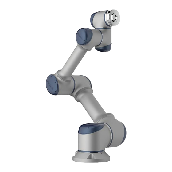
3 Introduction The following chapter will introduce how to operate the GCR20-1100 & GCR14-1400 collaborative robot. The user interface version is 2.2.14 and robot version is 1.2.15. -
Page 13: Power On & Power Off
4 Power On & Power off The power button is on the side of the control box. Plug in the 220VAC power cable and press down the power on button to enable the operation system. After pressing the power button, the indicator light will turns on. The system initialize till the welcome page appears on the demonstrator. - Page 14 System will show the robot installation orientation and flange loading information. For example, “Robot install: Longitudinal TCP load 0 kg”. If any information does NOT match with actual, for safety concern, please modify them from system setting before any other operations. These parameter settings will affect the zero-gravity manual jogging function and the collision detection function.
- Page 15 To disconnect the robot, click the “Disconnect” button from demonstrator home page top right corner. To shut off the system, click the switch off icon to completely shut off the system.
-
Page 16: User Interface Introduction
5 User Interface Introduction There are 7 tabs on the top of home page. It is called navigation bar. Each tab has an unique function, such as “Jog(manual move)”,” Program”,” Run”, “Status”, “Setting”, “About” and “Disconnect”. The default home page is “Jog” after power on the system. Jog Page Click the “Jog”... - Page 17 2. Coordinate Click Coordinate button will show the coordinate selection page. The robot will use base coordinate by default. Base coordinate is established at the bottom of the robot which is also indicated on the 3D robot view. If you have other attachment tool installed on the flange, you can also click Tool Coordinate or User Coordinate.
- Page 18 3. 3D View Click 3D View button to show the robot 3D simulation. The simulation is based on real robot. The simulation interface will show whether the robot is located at home position.
- Page 19 4. Joint Move Joint Move is set by default move joint. The blue progress bar shows the current joint position and the limitation for each joint. Hold left/right button to move forward and backward. Release the arrow button will stop at current move. The buttons 1-6 on the demonstrator correspond to the joints 1-6 here.
- Page 20 teach mode, it is able to jog the robot arm by human and move the arm quickly to the target point. Release the button to exit traction teach mode. While the robot is in traction teach mode, it is able to modify the drugging smooth by click the + or - button.
- Page 21 7. Speed Adjust Click Speed button will display the speed adjustment bar. It is able to modify joint speed, flange end speed and reset to home position speed. Speed can also be adjusted by the 7 “+” “-“ buttons on the teach pendant.
-
Page 22: Program Page
8. Home button To hold the Home button will move the robot to the home position, whereas releasing, it will pause current motion. The home position is set by default which each axis is located at 0 positions. 9. TCP Bias The TCP Bias button illustrates the flange end displacement at tool coordinate. - Page 23 The user is able to quickly open up a program to continuous editing, or preview a program that has been prepared before by clicking the Import button. In addition, it is able to copy or delete the program where listed at the left column of screen to an USB drive.
- Page 24 After entering the program name, a filename editing will appears. User can add movement nodes or script languages to the program in this page. The new created program will be named as: “siasun.spf”. Click the Finish Editing button to exit editing page.
-
Page 25: Run Page
Run Page Click Run to select a program. Click Start button to start run a program. Before running, system will detect if the first target move position is the current robot position or not. For safety concern, if these two positions are different, user must move the robot to the first target position manually by holding the Press to Move button. - Page 26 If the program is run by an external TCP command, the system won’t detect if current robot position is the initial position. Therefore, the program will automatically run in this case. After verifying the position, click the Start button again to run the program, or click Step button for executing the program step by step.
-
Page 27: Status Page
Status Page Click Status on the top navigation bar will open the status page. Status page will display current flange end position, current joint position, I/O status and log info. User can check the digital input status and digital output status from this page. Red dot means low level and blue dot means high level. - Page 28 There are 8 digital inputs and outputs on the control box and 2 digital inputs and outputs on the robot flange. It is able to swap high or low level by clicking the corresponding dot.
-
Page 29: Setting Page
Setting Page Click Setting on the top navigation bar will open the setting page. TCP Setting: From the tool coordinate setting, it is able to set up the displacement between tool... - Page 30 coordinate to the flange. Meanwhile, it is able to set up the gravity center location and weight. For quickly swapping to the correct coordinate from coordinate list, multiple tools coordinate can be saved. It is straightforward to calculate the load gravity center by robot. During the calculation, the robot 4, 5, and 6 axis rotate automatically following the algorithm has been developed.
- Page 31 For TCP calibration, first, select a point for TCP calibration. Second, move robot end to which the select point. Finally, click “Next” for the next select point.
- Page 32 By 4-point or 6-point method, please check the TCP has been set as 0. User Coordinate Setting: From user coordinate setting, it is able to set up the displacement between tool ends to base coordinate. It is able to save multiple tool coordinates.
- Page 33 Click User coordinate calibration to set up user coordinate with 3-point method. P1 is object coordinate origin; P2 and P3 are the X and Y direction of object coordinate respectively. The simulation result will show on demonstrator after all settings. Default Program: Default program setting will let the robot run a specific program automatically when the system starts.
- Page 34 dot beside the Default Program button, whereas a blue dot will appears. IP Address Setting: User is able to check robot’s IP address or set robot’s IP address in this function. User can use DHCP to auto affect an IP address or use a static IP address. Safety Setting: After type-in password, it is able to check whether the collision detection function is open or not.
- Page 35 Safety code is calculated by safety setting. It will be modified if there are any changes. When the system power on, there is a detection that compares setting difference. If the detection result is false, the robot will warning and let user to reset.
- Page 36 Virtual Wall: System can set up to 6 virtual walls, which includes 2 horizontal walls and 4 vertical walls. Horizontal walls need to enter the distance (mm) between the wall plane and the X-Y plane at the base coordinate. Vertical walls need to enter the distance (mm) between the wall plane and the Z axis of the base coordinate, and the rotation degree across the Z axis.
- Page 37 For example, here we create a horizontal wall with 1100mm distance to the X-Y plane. At the same time, create a vertical wall with 300mm distance to the Z axis, with rotation 45 degree counter clockwise. The wall in 3D view is like the capture below.
- Page 38 Restoration Protection type Description Method Protective Stop stop with break release Manual (1st type) robot may moves stop without break release Protective Stop robot will stay Manual/Auto (2nd type) where stopped safety decelerate reduce speed to safely speed Manual/Auto Advance Setting: The advance setting needs passwords to turn on.
- Page 39 Set Home Position is used to reset robot home position to where the robot actual position. Move robot to target home position and click this button if it requires changing home position. Change Password function is for reset password. Default password is 111. Software update function is for upgrade software.
-
Page 40: About Page
About Page Click About on the top navigation bar will open the about page. This page displays software version and company information. Disconnect Page Disconnect will disable the control of the robot. When clicked, robot will disconnect from control box, the joints brakes will stuck and the servos will be disabled. -
Page 41: Robot Programming
6 Robot Programming Create program Click Create Program and enter a program name. - Page 42 After creating a program, type in program name then click Enter. Only characters, numbers and underline are allowed for editing filename. The new created program will be named as: “siasun.spf”. Click the Finish Editing button to exit the edit page.
- Page 43 On the left side listed is the program display list. When create a new program, the system default set the first programming language as “movej”. In the program, each node represents a robot movement unit. When a new program starts, the robot will automatically move to the first script position, since the first “movej”...
- Page 44 After moving the robot to destination, click Save Position button to record a location. Afterwards, the interface turns back to setting page for further nodes setting. Click Move robot here, the robot moves to this point with each axis collaboratively. Click Add Nodes, the interface turns to add node page.
-
Page 45: Move Tab
Move tab movej:The robot arm move joints to the target position. The end trajectory is unknow. (Start node is a movej node) movel:The end of the arm move in a straight line. movej_Pose: For a selected location, robot moves to destination with constant speed for each axis. -
Page 46: Function Tab
list, the red dot means a path has been saved; whereas a blue dot means it is free to save a new path. If the red dot path space has been record twice, it will cover the previous path. Script language: The Script Language button let user to edit functions by pop-up keyboard. - Page 47 The functions illustrate below are functions for IO. The function illustrate below are logic function.
- Page 48 The functions illustrate below are function for coordinate establishment. The functions illustrate below are functions for printing...
- Page 49 The functions illustrate are functions for resulting critical robot parameter. The functions illustrate are Modbus functions.
-
Page 50: Socket Tab: Internet Communication Functions
Socket tab: internet communication functions The image above illustrates the shortcut functions. For the full function and function description, please refer to script description of internet communication. Variable Tab Establishment This tab is for establishing Pose variable and joint Array variable. It is record by traction teach with these two functions. -
Page 51: Example
Example Add a movej and movel node, respectively. Then add a MoveC node and set it’s sub-nodes position. - Page 52 Coordinate instruction If the coordinate has NOT been set up yet, the robot flange end function is represented by the displacement between the center of flange and the base coordinate origin. If the coordinate has been set up by coordinate_tool function, the following function parameter is represented by the displacement between tool coordinate origin and base coordinate.
-
Page 54: Robot External Communication Protocol
7 Robot External Communication Protocol TCP/IP: Robot is a unit of intercepted port for TCP server 2000 and TCP server 2001. Port 2000 receives control commands of the robot and sends feedback. Port 2001 sends out robot current status within 10HZ frequency. Port 2000: Port 2000 follows the request-to-respond mechanism. - Page 55 When robot finish any script, it will send <script finish> as feedback. Client sends <speed (speed_percentage)> to Server will change the speed percentage of current running program. The valid value area is in ( 0,100]. If successfully set, Server will return <speed set> to client, if not, Server will return <speed invalid>to client.
- Page 56 <poweroff success > and shut down the power; whereas robot has been powered off already, it will send <must disconnect first > to the client. Client sends <status> to Server, robot will send the 6 joints displacement between the end to the base coordinate origin, such as pos1 ; pos2 ; pos3 ; pos4 ; pos5 ; pos6 ;...
- Page 57 Name Type Variables Size Address Description joint actual double 0-47 6 joints actual position position reserved double 48-55 joint preset double 56-1033 6 joints preset position position reserved double 104-111 joint double 112-159 6 joints rotation speed speed reserved double 160-167 joint 6 joints rotation...
- Page 58 reserved double 696-703 kinematic robot kinematic robot terminal bool 704-751 terminal posture posture Control box digital digital input(1-10 reserved,11-14 bool 752-783 input system IO, 15-22 external input,23-32 reserved) Control box digital digital output(1-2reserved,3-8 bool 784-815 output system IO, 9-16 external input,7-32reserved) tool digital input(1-2 tool tool IO input...
- Page 59 robot status,hundrads place represent Home status."1" represent home position. The number as ones place represent as follow: Unconnected = 0, Power = 1, Initial = 2, robot status char Disable = 3, Enable = 4, Standstill = 5, Running = 6, Stopping = 7, Estop = 8, Error = 9,...
- Page 60 Modbus TCP: Robot is a Modbus Server waiting for connection from external Modbus clients. Robot Modbus setting: Colis: Read (number: 1) and Write (number: 5) R/W right Address Node Introduction locked running program standby paused program stopped (rising edge) error Control box IO output,io_out[1] Control box IO output,io_out[2] Control box IO output,io_out[3]...
- Page 61 robot standby robot running program robot stopped robot paused current program finished robot alert manual mode automatic mode robot at origin emergency stopped robot power on(rising edge) robot power off(rising edge) robot shutting down (disconnected, rising edge) run loading program(rising edge) pause program(rising edge) continue run program(rising edge) stop program(rising edge)
- Page 62 y position (base),low 16 bits y position (base),high 16 bits z position (base),low 16 bits z position (base),high 16 bits rx position (base),low 16 bits rx position (base),high 16 bits ry position (base),low 16 bits ry position (base),high 16 bits rz position (base),low 16 bits rz position (base),high 16 bits robot status,hundrads place represent Home...
-
Page 63: Script Language Guide
When a build-in arithmetic type is defined, the system will decide its type depending on its initial value. String Type: The system only supports constants of string type, such as "siasun robot". The string ends with ‘\0’. Pose Type: Pose type is an array with 6 float data. The system supports both constants and variables of pose type. -
Page 64: Variables
A string constant is a collection of characters. It ends with ‘\0’. The length of a string constant is the number of characters in the constant plus one. For example, "siasun robot", a string constant, actually contains 13 characters. String constants can be used to define character array variables or used as arguments transfer to functions. -
Page 65: Expression
#a1 is a integer array variable, has a length of 8 and is initialized to 0. a2 = Array(8, FLO); # a2 is a floating-point array variable, has a length of 8 and is initialized to 0.0. a3 = Array(7, INT, [1,2,3,4,5]); # a3 is a integer array variable, has a length of 7 and is initialized to [1,2,3,4,5,0,0]. -
Page 66: Assignment Expression
#if exp1 != 0, the expression returns 0. Otherwise, the expression returns 1. 8.3.4 Assignment Expression Variable name (id) = exp The value of an assignment expression is the representation of a variable. An expression is an assignment expression only if the variable has already been defined. -
Page 67: Return Statement
def fun1(pose:p, array:a, int:c, string:str): … Parameter Type: array: array type string: string type int: integer float: floating point Pose: pose type Return value type: int: integer float: float Custom functions are only used for mathematical operations. Motion functions and print functions are not supported in the system. -
Page 68: System Function Description
Form three: if (exp): … else : … Like most programming languages, the system supports if conditional control statements. When the decision conditional expression (exp) in if or elif is greater than 0, the contents of the statement block are executed. System Function Description 8.5.1 Movement Control movej( array : axis, float : v, float : a, float : rad = 0 );... - Page 69 v: It represents the joint angular velocity, whose unit is % (the percentage of speed set by the system).It has a value range of (0,100]. a: It represents the joint acceleration, whose unit is % (the percentage of acceleration set by the system).It has a value range of (0,100]. Return Value: none Movel( pose : p, float : v, float : a, float : rad = 0 );...
- Page 70 This command controls the robot to move linearly in the tool coordinate system. Parameters Description: pose_offset: The pose point, which is a floating-point array with a length of 6, corresponds to the pose offset in the tool coordinate system. v: It represents the robot end velocity in linear movement. Its unit is mm/s.
- Page 71 receives the speed_stop function. Parameters Description: axis_speed : It represents the joint angular velocity, whose unit is deg/s. Return Value: none speedl (pose : position_speed); Function Description: This command controls the robot end to move continuously at a given velocity. The subsequent commands are directly executed after the speedl function is executed.
-
Page 72: Tcp/Ip Socket Client
Return Value: none 8.5.2 TCP/IP Socket client socket_open( string : ip, int : port ); Function Description: This command is used to open an Ethernet communication link. If the creation is not successful within three seconds, the link creation fails. Parameters Description: ip : It represents the IP address of the server. - Page 73 a[0]=3.1416; a[1]=2.71828; socket_send_float ( a ); socket_send_int ( Array : array_send); Function Description: Send an integer array to the connected server. Parameters Description: array_send : It represents the integer array sent to the server. Each data in the array is 32 bits. Return Value: true or false Example...
- Page 74 receive : It represents the array that stores the floating-point numbers parsed by this function. All data in the string received from the connected server should be in (). Adjacent floating-point numbers should be separated by ",". For example: (1.23,3.1416,1.0) . Note that the maximum string length is 100.
- Page 75 in (). Adjacent integer numbers should be separated by ",". For example: (1.23,3.1416,1.0). Note that the maximum string length is 100. timeout : It represents the maximum waiting time for which the system can receive the string message. Its unit is ms. This value can be changed. It has a default value of 3000ms.
-
Page 76: System Functions And Peripherals
8.5.3 System Functions and Peripherals sleep( int : time ); Function Description: This command make the program pause for a certain time. Parameters Description: time : It represents the time to pause. Its unit is ms. Return Value: none io_out( int : portnum, int : val ); Function Description: This command controls the high and low levels of the IO output port on the control box. - Page 77 portnum : It represents the serial number of the IO input port on the control box. Its range is from 1 to 6. 1: Lock the robot lock 2: Start the program 3: Pause the program 4: Stop the program 5: Reserved 6: Reserved Return Value:...
- Page 78 portnum : It represents the serial number of the IO output port at the end of the robot. Its range is from 1 to 2. val : When the value is 1, the IO output port is at high level. When the value is 0, the IO output port is at low level.
- Page 79 Return 0 when the content of the internal bool register is false. Return -1 when the serial number of the internal bool register is wrong. Example print_i( r_reg_bool( 5 ) ); w_reg_byte( int : num, int : value ); Function Description: This command can change the value of the internal byte register.
- Page 80 Function Description: This command reads the value of the internal float register. Parameters Description: num : It represents the serial number of the internal float register. Its range is from 1 to 32. Return Value: Return the value stored by the internal float register. It is a floating-point number.
- Page 81 coordinate_clear(); Function Description: This command is used to cancel the coordinate system set before. The position in the subsequent motion function is based on the base coordinate system. Parameters Description: none Return Value: none set_tcp_load(float: tcpLoad, float loadBiasX, float loadBiasY, float loadBiasZ);...
- Page 82 Return Value: none get_flange_pose(pose : p); Function Description: This command can obtain the center pose of the robot flange end in the current state. Parameters Description: p : It represents the pose data in which the acquired pose are stored. Return Value: none get_tcp_pose(pose : p);...
-
Page 83: Debug Function
This command can open or close the collision detection. Parameters Description: status : When the value is 1, the collision detection is open. When the value is 0, the collision detection is closed. Otherwise, this command can’t change the status of the collision detection. Return Value: none 8.5.4 Debug Function... -
Page 84: Modbus
Parameters Description: s : It represents a string value. Return Value: none Example: s="siasun"; print_s(s); 8.5.5 Modbus modbus_read(string : signal_name); Function Description: This command can read the data of the modbus node. The return value of this command is an integer. - Page 85 value has a range from -32768 to 32767. Return Value: none Example: modbus_write_r(“mbus1”, 255); modbus_set_frequency(string : signal_name, int : frequence); Function Description: This command can change the refresh frequency of the modbus node. The default frequency is 10Hz. Parameters Description: signal_name : It represents the name of the modbus node.
- Page 86 signal_name : It represents the name of the modbus node. Return Value: none Example: modbus_delete_signal (“mbus1”);...
- Page 87 SIASUN Co., Ltd Add: NO.257 Jinzang Rd. Pudong New District, Shanghai, China Tel: +086-021-50870608 Fax: +086-021-63631363 Zip Code: 201206 http://www.siasun.com...
Need help?
Do you have a question about the GCR Series and is the answer not in the manual?
Questions and answers