
Related Manuals for SIASUN GCR20-1100


Summary of Contents for SIASUN GCR20-1100
- Page 1 GCR20-1100 Collaborative Robot User Manual (Hardware) Model: GCR20-1100 V2.0 SIASUN Co.,Ltd.
- Page 2 Your purchase of products, services or features, etc., shall be subject to the commercial contract and terms and conditions of SIASUN Co., Ltd. All or part of the products, services or features described in this manual may not be within the scope of your purchase or use. Unless otherwise agreed in the contract, SIASUN Co., Ltd.
-
Page 3: Table Of Contents
Content Preface................................1 Intended Audience ..........................1 Representation of Warnings and Notes ................... 2 Special Statement ..........................3 Revision History ..........................3 Safety ................................4 Abstract ............................. 4 Limitation of Liability ........................4 Risk Assessment ..........................5 Safety Operations ..........................6 2.4.1 Emergency Stop ........................ - Page 4 Installation and commissioning ........................36 Mechanical Installation ........................36 5.1.1 Base module Installation....................36 5.1.2 Tool Flange Installation ..................... 37 5.1.3 Control box installation ..................... 37 Electrical installation ........................38 5.2.1 Introduction ........................38 5.2.2 Electrical Warning and Cautions ..................38 5.2.3 Control Box I/O ........................
-
Page 5: Preface
1.1 Intended Audience This document provides operating instructions for the SIASUN Collaborative Robot GCR20-1100, so that users can learn more about the robot basic information and use the robot more safely and conveniently. Be sure to operate this robot on the basis of careful reading and full understanding of this document. -
Page 6: Representation Of Warnings And Notes
1.2 Representation of Warnings and Notes The table below defines general hazards related symbols, please read through the description carefully. Symbol Description Used to warn of emergency situations that, if not avoided, could result in death or serious personal injury. Used to warn of potentially dangerous situations that, if not avoided, could result in death or serious personal injury. -
Page 7: Special Statement
1.3 Special Statement This manual is only used as a guide. Its content (such as equipment appearance, software interface) is based on laboratory equipment information. The content provided in this manual is of general guidance and does not guarantee that all usage scenarios cover all models. -
Page 8: Safety
2 Safety 2.1 Abstract This section describes important safety and risk assessments that you need to be aware when installing, applying, and maintaining on robot and its components. The user must read and fully understand this information before the robot is powered on for the first time. -
Page 9: Risk Assessment
Label the integrator's logo and contact information on the installed robotic system. SIASUN Co., Ltd. is committed to providing reliable safety information, but does not assume responsibilities. It is important to declare that even if all operations are carried out in a safe manner, there is no guarantee that the robot system will not cause personal and property damage to the user. -
Page 10: Safety Operations
The following list identifies the significant risks that integrators must consider. Please note that there may be other significant hazards from certain robotic devices. Finger is clamped between joint 4 and joint 5; Sharp edges and sharp spots on the tool or the tool connector may cause damage to human skin;... - Page 11 Manual brake release: Remove the M3 screws that secure the joint cover and remove the joint cover. Press the plunger in the small electromagnet to release the brake. Manually moving the robot arm is limited to emergency situation and may damage joints. ...
-
Page 12: The Risk Of Collision
2.5 The Risk of Collision There is still a collision detection blind zone during the actual operation of the robot. Users must pay attention to the risk of collision detection failure under special working conditions. Typical three types of operating conditions are as follows. - Page 13 Image 2.4.2.2 Scenario 1: robot top view Scenario 2: Centering on the Z-direction of the robot base coordinate system, the radius is about 500mm. If the contact point is within this range, and the contact force direction is perpendicular to the plane of the joints of the joints 2 and joint 3, the collision detection function is difficult to detect collisions between the robot and the outside world.
- Page 14 Image 2.4.2.4 Scenario 2: robot front view Scenario 3: When the robot collides with the outside world, and if the collision point is located in the spherical range with a radius of about 500mm centered on the robot base, the robot is more difficult to detect the collision regardless of the pose and state of the robot.
- Page 15 Image 2.4.2.6 Scenario 3: robot front view For all the above described scenarios, if the robot moves in a direction that is insensitive to external collision detection, considering the limitation of the cooperation between the robot and the outside world, the running speed at this time should be reduced as much as possible.
-
Page 16: Production Introduction
3 Production Introduction 3.1 Overview The collaborative robot system consists of the following parts: GCR20-1100 robot Control box Demonstrator Cables Software Optional accessories Image 3.1.1 Robot system schemata System critical parameters Degree of freedom: 6 Operational temperature:0℃... -
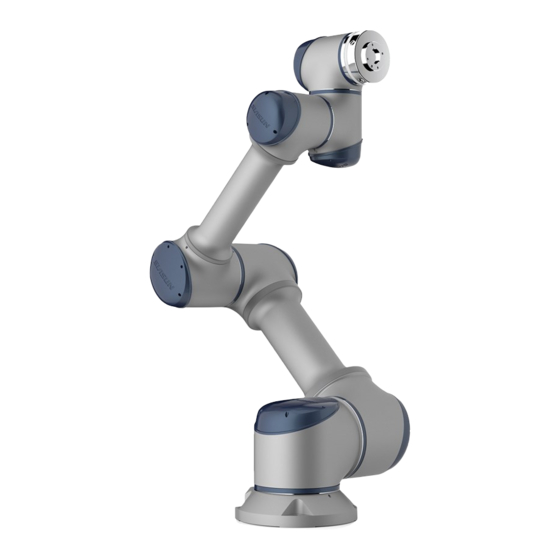
Page 17: Robot
3.2 Robot 3.2.1 Introduction The SIASUN collaborative robot GCR20-1100 consists of 6 modular joints. The total length of robotic arm is 1260.5mm, workspace radius 1100mm, with traction teaching, visual guidance, collision detection and other functions. Each joint of the robot is equipped with a position sensor to detect the joint operation position and equipped with a reliable brake to stop it in time. -
Page 18: Base Input Panel Description
3.2.2 Base Input Panel Description ① ③ ② schemata Image3.2.22 Base module The base input panel is located at the bottom of the robot and contains several functional ports. Used to connect cables, supply power to robots, transmit data, and connect gas lines. Base input panel includes the following functional ports: AIR (φ4) Thread hole Expansion port(RS 485)... -
Page 19: Tool Flange
3.2.3 Tool Flange The flange is on the end of robot, which follow GB/T14468.1-50-4-M6 or ISO 9409-1-50-4-M6 standard. There are mounting thread holes and pin holes for tools installation on the flange. The expansion I / O port on the flange can be used for connecting tools. - Page 20 The indicator light described as follow: Description Color Image demo 1.Robot power on Constant 2.Standby blue Flashing Error detected 1.Running program 2.Robot 0 position Constant 3.Manually move to any point green 4.Collection detected Flashing Traction teach green Flashing Robot power on white...
-
Page 21: Control System
3.3 Control System Control system consists of robot controller and teach pendant. Control system overview is as following: ③ ⑥ ② ④ ⑤ ① ⑦ ① ② Brake board ③ Power supply ④ Peripheral modules ⑤ Main controller ⑥ Demonstrator ⑦... -
Page 22: Control Box
3.4 Control Box 3.4.1 Introduction The controller contains the power distribution unit and communication port for all components of the robot control system. The controller contains the main controller, power supply, peripheral port module, brake system. The power supply is divided into two parts: control system power supply and motion module power supply. -
Page 23: Control Box External Interface
3.4.3 Control Box External Interface External port 1 RJ45 port2 RJ45 port1 Emergency DVI-D ON/OFF stop port I/O ports USB port External port 2 Robot port RJ45 port3 Demonstrator System 220VAC port power power port Supply port External port 1( system power adaptor and peripheral input) External port 1 is a port for system power adaptor and peripheral data input such as emergency stop input and output, robot automatic run feedback input and output and etc. - Page 24 Robot port Robot port connects between robot and control box. Emergency stop Emergency stop is a button for emergency situation while pressing the robot will stop any motion immediately. Demonstrator port Demonstrator port connect control box for further robot controls. RJ45-2 port RJ45-2 port connects principle computer with control box.
-
Page 25: Control Box Power Supply Cable
3.4.4 Control Box Power Supply Cable When the control cabinet is powered by 220V, the maximum power is 3000W, and the standard 16A power plug is used as the power supply cable plug of the control box. The standard power supply cable of the control box is 5m long, and other standard length power supply cables are available for purchase. -
Page 26: Demonstrator
3.5 Demonstrator Teach pendant is a handheld programmer monitor for robotic systems that has various operating and display functions required for robot system operation and programming. Image3.4.45 Demonstrator ① Automatic/manual mode switch ② Power on/off button ③ Emergency stop ④ Joint movement buttons Enabling button (unused)... -
Page 27: Technical Data
4 Technical Data 4.1 Robot Technical Data 4.1.1 Basic Data Label Data Load 20kg Degree of freedom Weight 52kg Workspace Radium 1100mm ±0.05mm Repeatability Joint Range Max Velocity(°/s) 137.5mm +180° to -180 ° 462.5mm +180° to -180 ° +180° to -180 ° 500mm +160°... -
Page 28: Working Space
4.1.2 Working Space The work space shape and size are as following: Top View Front View Image 4.1.2 Robot work space... -
Page 29: Robot Joint Coordinates
4.1.3 Robot joint coordinates Robot joint coordinate schemata as follow: Figure 4.1.3.1 Robot joint coordinate schemata 4.1.4 Robot zero position and positive direction Robot zero position and positive direction is illustrated as follow:... - Page 30 Figure 4.1.4.1 Robot zero position and positive direction schemata...
-
Page 31: Tool Flange Data
4.1.5 Tool Flange Data Basic data Load 20 kg EMC Resistance EN 61000-6-2 and EN 61000-6-4 IP code IP 54 Bolt level 12.9 Bolt size GB/T 14468.1-50-4- M6 Standards ISO 9409-1-50-4-M6... -
Page 32: Base Data
4.1.6 Base Data The specific forces and moments required to mount the base are given below, the robot's load and inertial force (weight) are included. Front View Top View Image 4.1.6 Robot base installation Force type Force/moment Vertical force, Fv 1160 N Horizontal force, Fh 1212N... -
Page 33: Load
Load 4.2.1 Basic Load data Rated load 20kg Moment of inertia allowance 1.0 kgm² 71.4mm Distance of load gravity center, Lxy Distance of load gravity center, Lz 15.4 mm... -
Page 34: Payload Diagram
According to the corresponding operation and programming guide, it is necessary to input the load and moment of inertia into the robot control system when operating the robot into operation. GCR20-1100 Payload Diagram Lxy (mm) 150.0... -
Page 35: Control System Technical Data
4.3 Control System Technical Data Basic parameters Color Ash black Weight 31kg IP code IP 30 Cooling system Forced air cooling Power connection Power input 230VAC ( -15% ~ +10%) Power frequency 50-60Hz Rated input power 3000W Environmental conditions Operating temperature 0~25℃... -
Page 36: Stop Time And Distance
4.5 Stop time and distance 4.5.1 Introduction General break information: Stop distance refers to the angle rotated from receiving the stop signal to fully stopped status. Stop time refers to the duration from the robot receives stop signal to fully stopped status. - Page 37 Axis Stop distance(deg) Stop time(ms) 10.7213 11.5897 16.4914...
-
Page 38: Nameplates And Labels
4.6 Nameplates and Labels The following nameplates and labels are attached to the robot and control box. It is not allowed to remove or unrecognized it. Unrecognized nameplates and labels must be replaced. - Page 39 Image Nameplates and labels...
-
Page 40: Installation And Commissioning
5 Installation and commissioning This chapter contains installation instruction and basic robot arrangement information. It mainly introduces that the installation instruction and basic precautions. The installation information includes both machinery and electrical components. Mechanical Installation 5.1.1 Base module Installation The robot on robot body is fixed by four M10 bolts through four 10.5mm screw holes on the base. -
Page 41: Tool Flange Installation
overall acceleration should be as low as possible. High accelerated place may accidentally stop the robot since the robot may report as collision detected. Make sure the robot has been fully installed. The installation surface must be vibration free. 5.1.2 Tool Flange Installation The tool flange of the robot has four M6 threaded holes for connecting the tool to the robot 10N•m torque is recommended to be used to fix these threaded holes. -
Page 42: Electrical Installation
5.2 Electrical installation 5.2.1 Introduction This section describes all the electrical interfaces of the robot body and control box. These interfaces are divided into five categories; each type of interface has different uses and attributes: Control box I/O Tool I/O ... - Page 43 Please ensure that all the equipment that is not water-stained remains dry. If water gets in the product, cut off the power and contact the supplier; Only use the robot's original cable. Do not use the robot in applications where the cable needs to be bent.
-
Page 44: Control Box I/O
5.2.3 Control Box I/O This section describes the controller I / O required for robot installation. It is extremely flexible and can be used on many different devices, including pneumatic relays, PLCs and emergency stop buttons. External port 1 It is a port for providing system power, peripheral extension in/out, emergency stop status in/out and etc. - Page 45 System function extension port 1 schemata The relationship between the system power-on interface and the system power-on input expansion interface is shown in the following figure. The two switches are in parallel relationship. The power-on switch uses the reset button. Power on sequence of robot system: Connect 220VAC input and power supply →...
- Page 46 I/O expansion interface I / O expansion for the control box provide external DI (PNP), DO(PNP,24V 24V/Max:500mA), and optional AI and AO. The port has been defined as follow: Port number Signal Robot locked(DI) Run program(DI) Paused(DI) Stopped(DI) Reserved(DI) Reserved(DI) Locked status(DO) Run program status(DO) Standby status(DO)
- Page 47 Others reserved...
- Page 48 I/O external port wiring diagram I/O extension schemata External port 2(Safety input and feedback) Safety input and feedback port is an external safety input port and safety input feedback port. The port has been defined as follow: Port number Description Safety input1-1+ Safety input 1-1- Safety input 1-2+...
- Page 49 Safety feedback output 2-1+ Safety feedback output 2-2+ Safety feedback output 2-2- Safety feedback output 2-1- Safety feedback output 1-1+ Safety feedback output 1-2+ Safety feedback output 1-2- Safety feedback output 1-1- Safety input and feedback...
- Page 50 Robot port Robot port connects control box and robot. The port is defined as follow: Port label Description EtherCAT Tx+ EtherCAT Tx- EtherCAT Rx+ EtherCAT Rx- RS485+ RS485-...
-
Page 51: Tool Flange I/O
5.2.4 Tool Flange I/O At the tool end of the robot, there are two small 8-pin connectors, see ① in the figure below. ① ② ③ ④ ⑤ ⑥ Image5.2.4 Tool flange schemata ① Expansion I/O port1 ② Screwed hole ③... - Page 52 GN (green3) Tool IO digital input2(DI1) WH(white1) BN (brown2) Tool IO and control box power are separated. The corresponding 24V and 0V (GND) must be separated as well. If there is need, for external and tool IO uses, please separate uses effectively by relays.
-
Page 53: Transportation And Storage
6 Transportation and storage 6.1 Transportation 6.1.1 Preconditions Robot: Maintaining the original packaging during transport, the packaging materials stored in a dry place. It may be necessary to pack and move the robot afterwards. Move the robot from the packaging material to the installation position while lifting the robot link. -
Page 54: Packaging Pose
robot and control box are oriented correctly. Robot Control box, demonstrator, cable Package1 Package2 robot packaging 6.1.3 Packaging Pose Before packaging, the robot requires to move to packaging position. The packaging position is defined as below:... -
Page 55: Packaging Size
Joint Angle(°) ° ° ° ° ° ° 6.1.4 Packaging Size The packaging box size provided is as follows. Packaging box size: 1050 x 550 x 725 mm... -
Page 56: Storage
6.2 Storage 6.2.1 Preconditions The following should be considered before long time storage: Storage location should be dry and dust-free Avoid temperature fluctuations Avoid condensation water Avoid direct sunlight Avoid air flow Choose a reasonable storage temperature range ... -
Page 57: Maintenance And Repair
7 Maintenance and repair All maintenance instructions in this manual must be strictly observed. Maintenance, calibration, repair must be based on the latest service manual. 7.1 Safety Instructions After maintenance, you must verify the system's security level. Check with valid standards and safety laws and regulations. - Page 58 Precautions: Do not change any information in the software security configuration (such as force limitation). Security configuration is described in the manual. If the safety parameters have been modified, the entire robot system should be considered a new system, which means that all safety audits, such as risk assessment, must be updated.
-
Page 59: Maintenance
7.2 Maintenance After the completion of equipment commissioning, maintenance should be carried out in accordance with the provisions of the maintenance period. Maintenance Term Regulations Form Reference Maintenance activities Documents Cleaning activities Clean the control box Clean the robot Check activities Check the robot Check the information label and nameplate... -
Page 60: Robot Cleaning
7.2.1 Robot Cleaning The dust/dirt/oil on the robot surface can be wiped off with a clean cloth and water or 10% ethanol. In some extreme cases, very small amount of grease can be visible from thejoint, which does not affect the function and lifetime of the joint.. -
Page 61: Repair
7.3 Repair Only trained users should allow for repairs on the robot controller. Repairs within equipment components should only be carried out by professionally trained personnel. Maintenance must be based on the latest service manual. Maintenance must be performed by an authorized system integrator or robot manufacturer. -
Page 62: Appendix A Reference
Appendix A Reference The following listed is reference: Standard No. Description Version GB 5226.1 Electrical safety of machinery 2008 Safety of machinery – general principles for design GB/T 15706 2012 Risk assessment and risk reduction GB 11291.1 Robots industrial environments- safety 2011 requirements... - Page 63 SIASUN Co., Ltd Add: NO.257 Jinzang Rd. Pudong New District, Shanghai, China Tel: +086-021-50870608 Fax: +086-021-63631363 Zip Code: 201206 http://www.siasun.com...
Need help?
Do you have a question about the GCR20-1100 and is the answer not in the manual?
Questions and answers