Table of Contents
Advertisement
Quick Links
Advertisement
Table of Contents

Related Manuals for Techroutes S3756


Summary of Contents for Techroutes S3756
- Page 1 S3756 Hardware Installation Manual...
-
Page 2: Table Of Contents
2.3.3 Cabinet Configuration ....................7 2.3.4 Power Requirements ....................8 2.4 Installation Tools and Device ....................Chapter 3 Installing the S3756 Switch ..................10 3.1 Installation Flow of S3756 ....................10 3.2 Installing the Machine Box of the Switch ................10... - Page 3 3.2.1 Installing the Machine Box on the Desk ..............10 3.2.2 Installing the Machine Box on the Cabinet .............. 11 3.3 Connecting the Port ......................11 3.3.1 Connecting the Console Port ................... 11 3.3.2 Connecting 10G Ethernet SFP+ Ports ..............13 Table of Contents 3.3.3 Connecting Ethernet TX Ports .................
- Page 4 5.2 Indicator Description ......................19...
-
Page 5: Chapter 1 S3756 Switch Introduction
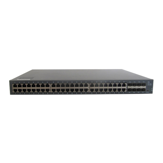
The section describes the characteristics and parameters of S3756 and gives an overview of S3756. 1.1 Appearance Description for Standard Configuration The built-in ports of S3756 are: 48 gigabit Ethernet RJ45 ports, 8 10G Ethernet SFP+ ports, 1 Console port. See table 1-1. Table 1-1 Attributes of the built-in port... -
Page 6: S3756 Systematic Characteristic Parameters
S3756 Hardware Installation Manual 8 gigabit SFP+ ports 48 gigabit RJ45 TX ports Figure 1-2 The back template of the S3756 switch Table 1-3 Parts at the back template of the S3756 switch Abbrev. Name Description AC power socket AC100~240V The grounding column The grounding column must be fine. - Page 7 S3756 Hardware Installation Manual 48 10/100/1000BASE-T ports 8 10G Ethernet SFP+ ports Standard configuration 1 Console port 442.50×350×44 Dimensions mm (W×D×H) Operating temperature/humidity 0℃ ~40℃ ; 10%~85% non-condensation Storage temperature/humidity -40℃ ~80℃ ; 5%~95% non-condensation Input voltage: , Input frequency: AC100~240V...
-
Page 8: Rohs Description
Similar to other electronic products, the semiconductor chip easily gets damaged if you power on or off abruptly and frequently. To restart up the switch of S3756, you have to open the power on- off after the power is cut down for three to five seconds. -
Page 9: Safety Advice
S3756 Hardware Installation Manual Use correct outside ports to connect the switch of S3756. Do not put the Ethernet plug into the console port (RJ45 8-line socket). Similarly, do not put the console cable into the console port (RJ45 8-line socket). -
Page 10: Electrostatic Discharge Damage Prevention
S3756 Hardware Installation Manual Pull out the AC power socket and close the direct-current power before operating on the machine box or working beside the power source. When the power is on, do not touch the power. ... -
Page 11: Environment
S3756 Hardware Installation Manual 2.3.1 Environment The switch can be installed on the desk or the cabinet. The location of the machine box, cabinet planning and indoor cabling are very important for normal system’s function. Short distance between devices, bad ventilation and untouchable control plate will cause maintenance problems, systematic faulty and breakdown. -
Page 12: Power Requirements
2.4 Installation Tools and Device The tools and devices to install the S3756 switch are not provided by the S3756 switch. You yourself need to prepare them. The following are the tools and devices needed for the typical installation of the S3756 switch: ... -
Page 13: Chapter 3 Installing The S3756 Switch
Installing the machine box on the desk Installing the machine box on the cabinet 3.2.1 Installing the Machine Box on the Desk The S3756 switch can be directly put on the smooth and safe desk. - 9 -... -
Page 14: Installing The Machine Box On The Cabinet
USB plug. After you connect the console port to the serial port of PC through a console cable, you can configure and monitor the switch of S3756 by running a terminal emulation software, such as super Windows terminal. The cable is provided according to the host. The communication... - Page 15 Otherwise, the single-pass problem will arise on the super terminal. The cable is used to connect the console port of S3756 and the outside console terminal device. One end of the cable is a Mini USB plug and the other end is a 9-hole plug (DB9). The Mini USB is put into the socket of the console port on S3756.
-
Page 16: Connecting 10G Ethernet Sfp+ Ports
Figure 3-4 RLC8501 3.3.2 Connecting 10G Ethernet SFP+ Ports S3756 switch has 8 10G SFP+ ports. Each port has its corresponding indicator: TE1~TE8. You can connect the SFP+ optical module to the SFP+ port and then you can connect other Ethernet terminal devices through the optical cable. - Page 17 See figure 3-7. Figure 3-6 RJ-45 connector on the console port Because the 48 10/100/1000Base-T ports of S3756 support the MDI/MDIX self-identification of the cable, S3756 can adopt five types of direct-through/cross network cables when it connects other Ethernet terminals. Figure 3-7 Connecting the 1000Base-TX port and other Ethernet terminals Note: The machine in the figure does not represent the material S3756.
-
Page 18: Checking After Installation
S3756 Hardware Installation Manual Sending/receiving the normal phase of data 1 TP1+ Sending/receiving the normal phase of data 2 TP2+ Sending/receiving the paraphase of the data 2 TP2- Sending/receiving the paraphase of the data 1 TP1- Sending/receiving the normal phase of data 3... -
Page 19: Chapter 4 Maintaining Switch
S3756 Hardware Installation Manual Chapter 4 Maintaining Switch Caution: Before opening the machine box, make sure that you have released the static you carried and then turn off the power on-off of the switch. Before operating any step in Appendix B, read the section “Safety Advice”. -
Page 20: Closing Machine Box
S3756 Hardware Installation Manual When the cover is opened, put it aside. The mainboard of the system appears. Note: After taking off the cover, put it horizontally and avoid it to be crushed or collided. Otherwise, the machine box is hard to install. -
Page 21: Fault Separation
9600 bps, eight data bits, no sum check bit, one stop bit and no traffic control. 5.2 Indicator Description The following table shows the indicators of the S3756 switch and their description: - 17 -... - Page 22 S3756 Hardware Installation Manual No. Abbrev. Name Description Power indicator When the switch is powered on, the indicator is on. System indicator When the indicator is always on, the system is being started up. When the indicator flickers, the system works well.
Need help?
Do you have a question about the S3756 and is the answer not in the manual?
Questions and answers