
Related Manuals for FUJI CONTROLS IN-100


Summary of Contents for FUJI CONTROLS IN-100
- Page 1 IN-100 INSTRUCTION MANUAL Ver. 1.05 Fuji Controls Co., Ltd. 1-5-6 Iidabashi, Chiyoda-ku, Tokyo 102-0072 TEL: 03-3265-5437 FAX: 03-3265-5430 Website: http://www.fujicon.net Feb 22, 2018...
-
Page 2: Introduction
Introduction Thank you for purchasing IN-100. Please thoroughly read this Manual to make a full use of IN-100. We also recommend storing this Manual for ready use whenever necessary. Features CC-Link capability equipped as a standard feature Compatible with 12 to 24 VDC power input ... -
Page 3: Accessories
Accessories Please contact the retailer or Fuji Controls if any accessory listed below is missing or damaged. Item Check Micro driver (−) Input/output connector (load cell terminal, external 1 each input/output terminal) Panel mounting jig (panel pre-mounted to the body proper) -
Page 4: Safety Instructions
Safety Instructions This Manual provides precautions and instructions to be complied with by users of this Product so users may safely and properly use the Product. Use the Product based on understanding of these instructions. Warnings Be aware of potential risks to users of the Product, including death or serious injury, associated with the following items. -
Page 5: Cautions
Cautions The following items represent situations or conditions where injury to humans or physical properties is expected. When conducting any of the following, be sure to remove the power plug or power cable: Wiring, cabling or connection of DC power, load cells, external input/output terminals, or terminal block to which to connect CC-Link ... - Page 6 When the top cover or panel surface becomes dirty, remove the dirt with a soft cloth soaked with a small amount of diluted neutral detergent and wipe it with a tightly squeezed damp cloth. Do not use wipes or cloths soaked with thinner. If the Product is used in ways not originally intended, safety may be compromised.
-
Page 7: Table Of Contents
Table of Contents Introduction ........................2 Features ........................2 Disclaimer ......................... 2 Accessories ....................... 3 Safety Instructions ......................4 Warnings ........................4 Cautions ........................5 Appearance ........................ 12 Front Nomenclature and Functions ................. 12 Rear Nomenclature and Functions ................13 Load Cell Terminal .................... - Page 8 Connecting to Input/Output Terminal Block .............. 20 Load Cell Terminal and External Input/Output Terminal ........20 Power Source ...................... 21 How to Use ......................... 22 Supplying Power ..................... 22 Key Locking......................22 Setting Lock ......................22 Screen ........................23 Names and Functions ..................... 23 Menu List ........................
- Page 9 Address Map ......................32 Remote Resister ....................32 Commands ......................35 Usage of CC-Link ....................38 Load Data ......................38 Memory Selection ....................38 Changing Exclusive Area Values................39 Reading/Writing Using Commands in Common Area ........... 40 List of CC-Link Error Codes ..................42 Setting ........................
- Page 10 What is "Select Data Output"? ................47 How to set ......................47 Comp. Value Setting ....................48 What is "Comp. Value Setting"? ................48 How to set ......................48 Hold Mode ....................... 49 What is "Hold Mode"? ..................49 How to set ......................49 Hold mode selection ....................
- Page 11 Changing Power Save Time ..................57 What is "Power Save Time"? ................57 How to set ......................57 CC-Link ........................58 What is "CC-Link"? ....................58 How to set ......................58 Languages ......................59 What is "Languages"? ..................59 How to set ......................59 List of Error Messages ....................
-
Page 12: Appearance
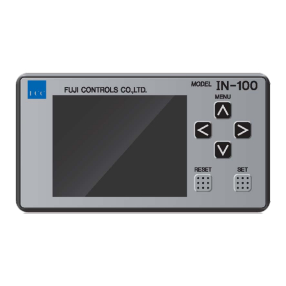
Appearance Front Nomenclature and Functions MENU key Cursor keys RESET key SET key Display Name Function MENU key When the instruction screen appears, press MENU key for setting screen. ⋀ ⋁ Cursor keys keys to move the cursor or change the settings. <... -
Page 13: Rear Nomenclature And Functions
Rear Nomenclature and Functions Load cell terminal External input/output terminal CC-Link terminal Power terminal Load Cell Terminal Terminal Function name Not in use. Do not connect. Not in use. Do not connect. +EXC Connect +EXC of load cell. −SIG Connect −SIG of load cell. −EXC Connect −EXC of load cell. -
Page 14: External Input/Output Terminal
External Input/Output Terminal Input/ Terminal Function output name V-OUT Analog voltage output terminal. I-OUT Analog current output terminal. Analog COM terminal for analog voltage and current voltage. output Do not short-circuit external input/output terminals Nos. 18 and 24. RESET Clears judgment results and sets digital zero. Constantly outputs comparison results. -
Page 15: Cc-Link Terminal
Connect to DG of CC-Link. Connect to SLD of CC-Link. Power Terminal Terminal Function name DC + input IN-100 power terminal. Connect 12 to 24 VDC. − DC − input Frame DC power frame ground terminal. Be sure to connect it. ground Input/Output Circuit... -
Page 16: How To Install
How to Install Appearance and Dimensions Rear view Front view... -
Page 17: Panel Mounting
Panel Mounting Size of Mounting Hole Recommended panel thickness is 0.8 to 5.0 mm. Panel Mounting Remove both the left and right panel mounting jigs. - Page 18 Set IN-100 in through the panel front. Attach left and right panel mounting jigs removed in 1 to the Product rear and fix them.
-
Page 19: Din Rail Installation
DIN Rail Installation Install the DIN rail mounting adapter to IN-100. Insert the DIN rail adapter diagonally and fix it. DIN rail... -
Page 20: Connection
Insert the wire in the insertion hole without untwisting the wire end. Pull out the micro driver. Slightly pull the wire to confirm the wire has been firmly clamped. Insert the connected plug to IN-100 and fix it with screws. -
Page 21: Power Source
Power Source DC power input voltage is between 12 and 24 V. Connect it to the terminal block with crimping terminals (for M3; 6 mm or under in width). It takes 10 seconds from power input to display start. Be sure to attach the terminal cover to prevent risk of fire or electric shock. -
Page 22: How To Use
Supplying Power Confirm the wires are correctly connected. IN-100 has no power switch. Use an external switch or a circuit protector. GO output turns on 10 seconds after power input, and display turns on. When GO output is turned off, start using the Product. -
Page 23: Screen
Screen Names and Functions Hold mode Judgment point display Judgment result Setting memory number Bar display Load value Lock display High and low limit setting Name Function Judgment point Turns on while held. display Displays SAMPLE in sample hold mode, PEAK in peak hold Hold Mode mode. -
Page 24: Menu List
Menu List Major category Item Reference page Filter Page 43 Control Input Check Page 44 Condition Judge Output Check Page 45 Setting Static Strain Disp. Mode Page 46 Select Data Output Page 47 Comparison Comp. Value Setting Page 48 Setting Hold Function Hold Mode... -
Page 25: Measurement Of Load
Measurement of Load When Constant Comparison Is OFF What is "constant comparison OFF" When external input/output terminal No. 13 FREE is OFF (HIGH), external input/output terminal No. 12 RESET is ON (LOW), edge is detected, hold load value is cleared, judgment result is cleared, digital zero is set, and measurement starts. -
Page 26: Sample Hold
Sample Hold DESCRIPTION OF OPERATIONS This function displays load values from the start to the end of measurement in real time. It holds the value just when measurement was completed and outputs the judgment result. OPERATION FLOW Actual load OF value HI value Display value c... -
Page 27: Peak Hold
Peak Hold DESCRIPTION OF OPERATIONS This functions measures peak loads from the start to end of measurement. It holds the value just until measurement is completed and outputs the judgment result. OPERATION FLOW Actual load OF value HI value Display value LO value Point Operation... -
Page 28: When Constant Comparison Is On
When Constant Comparison Is ON What is "constant comparison ON"? When external input/output terminal No. 13 FREE is ON (LOW), external input/output terminal No. 12 RESET is ON (LOW), edge is detected, hold load value is cleared, digital zero is set, and measurement starts. Judgment results are output in real time. -
Page 29: Sample Hold
Sample Hold DESCRIPTION OF OPERATIONS This functions measures loads in real time from the start of measurement and outputs the judgment result in real time. OPERATION FLOW Actual load OF value HI value Dispslay value LO value Point Operation LO output ON END input (holding of value) Release of END (release of value holding) HI output ON... -
Page 30: Peak Hold
Peak Hold DESCRIPTION OF OPERATIONS This function measures peak loads from the start of measurement to the start of next measurement. OPERATION FLOW Actual load OF value HI value Display value LO value Point Operation LO output ON END input (holding of value) Release of END (release of value holding) HI output ON OF output ON... -
Page 31: Cc-Link Communication
CC-Link Communication Wire-saving feature of CC-Link allows any input/output of IN-100 to be turned on or off or acquire hold load values or real time load values. CC-Link version of IN-100 is 1.10, and the type of station is remote device station. -
Page 32: Connecting Cc-Link Terminal
Connecting CC-Link Terminal Use a dedicated cable for CC-Link for connection cable. Connect the shield to SLD terminal. Connect the end resistance between DA and DB. Be sure to turn off power prior to wiring. Be sure to put the terminal cover on after wiring. Be aware that CC-Link receives commands only from the measurement display screen. - Page 33 INPUT/OUTPUT Station Output Address Name Input Address Name Respond to Exclusive Request Exclusive RX0000 RY0000 area area RX0001 RY0001 Respond to Common Request Common RX0002 RY0002 area area RX0003 Respond to R/W RY0003 Request R/W RX0004 RY0004 RX0005 RY0005 RX0006 RY0006 RX0007 CPU normal...
- Page 34 RX0020 0x0E2 RY0020 0x162 │ │ │ │ │ Reserved Reserved RX005F 0x0E5 RY005F 0x165 RX0060 RY0060 │ │ 0x0E6 Reserved 0x166 RX006F RY006F RX0070 RY0070 │ │ Reserved RX0079 RY0079 Reserved RX007A Error status flag RY007A 0x0E7 0x167 RX007B Remote Ready RY007B RX007C...
-
Page 35: Commands
Commands See Page 40 Reading/Writing Using Commands in Common Area for usage. Function Group Setting name Command no. Setting RESET 0000 0000 Execution Measurement screen 0000 Static strain display 0000 0: Voltage D/A Output Mode 1301 1: Current D/A MAX. Voltage 1302 1~10 Convertor... - Page 36 manual. 0: By menu Hold mode 4901 selection 1: By signal...
- Page 37 0: By menu 5001 1: By signal 0: Memory 1 Setting Memory 1: Memory 2 5002 2: Memory 3 3: Memory 4 0: Standard Control input 5901 logic 1: Reversed Station Type 5101 0: 4 Station Station Number 5102 1 to 64 0: 156 kbps 1: 625 kbps Transmission Speed...
-
Page 38: Usage Of Cc-Link
Usage of CC-Link Load Data For hold load values and real time load values, data format changes by setting either BCD or Binary at Return Data Format. See Page 58 CC-Link for the setting procedure. Real time load value and hold load value 4 bits Status See the following figure. -
Page 39: Changing Exclusive Area Values
Changing Exclusive Area Values Confirm that Request Exclusive area, Respond to Exclusive area, Request Common area, and Respond to Common area are all OFF. When Request Exclusive area is ON, the Product judges that writing of Exclusive area data has been requested and starts writing of Exclusive area data. When writing of Exclusive area data is completed, Respond to Exclusive area is ON. -
Page 40: Reading/Writing Using Commands In Common Area
Respond to Common area are all OFF. Then conduct the following process. When Request Common area is ON, IN-100 judges whether it is "write" or "read" that it should execute depending on ON or OFF of R/W and then executes the command. - Page 41 WRITE Write the command no. value in Write command no. Set values in 16-bit BCD. Write the target value in Write command data. Set values as 32-bit signed binary values. Turn OFF Request R/W. Confirm Respond to R/W is OFF. Turn ON Request Common area.
-
Page 42: List Of Cc-Link Error Codes
List of CC-Link Error Codes Support error State Error code Description code Normal Normal Equipment error System error Error has occurred in calibration processing. Calibration error Calibration lock has been set. No calibration conducted. −FULL (lower than the minimum setting display value) +FULL (higher than the maximum setting display value) -
Page 43: Setting
Setting Filter What is "Filter"? When load value is unstable, set a low-path filter or the number of moving average to stabilize the load value. A low-path filter can remove instantaneous changes such as external noises and stabilize load values. The function of the number of moving average calculates the average of loads for the set number to stabilize the load value. -
Page 44: Control Input Check
Control Input Check What is "Control Input Check"? It can check ON or OFF status of each input. When the signal is OFF, the display is HIGH. When it is ON, the display is LOW. You cannot manually turn ON or OFF on the screen. How to set Press MENU key. -
Page 45: Judge Output Check
Judge Output Check What is "Judge Output Check"? This function allows the user to turn on or off Judge Output manually from IN-100 body proper and check wiring. OF is a set value load output signal, HI load HI-NG output, GO a load GOOD output, LO a load LO-NG output, and OV a load cell anomaly output. -
Page 46: Static Strain Disp. Mode
Static Strain Disp. Mode What is the "Static Strain Disp. Mode"? It allows you to display static strain in μST (micro strain), the strain amount unit of load cell. It is used to survey defects, such as eternal strain of load cell. When a load value is dubious, check the value and contact us. -
Page 47: Select Data Output
Select Data Output What is "Select Data Output"? IN-100 is fitted with the analog output function. You can select analog output mode. When Output Hold Value is selected, voltage or current values interlinked with the display value are output in an analogous way. -
Page 48: Comp. Value Setting
Comp. Value Setting What is "Comp. Value Setting"? It allows you to set each of set load arrival output, high limit judgment value, and low limit judgment value. OF value is a set load arrival output, HI is a high limit judgment value, and LO is a low limit judgment value. -
Page 49: Hold Mode
Hold Mode What is "Hold Mode"? This function allows you to select how to display a value from the beginning to the end of load measurement. When By menu is set by Hold mode selection, the mode of load value display is switched over between the peak hold mode and the sample hold mode. -
Page 50: Hold Mode Selection
When By menu is selected, the mode set by the Hold Mode is effective. When By signal is selected, set IN-100's external input/output terminal No. 15 MODE to OFF (HIGH) to set the sample hold mode and to ON (LOW) to set the peak hold mode. -
Page 51: Setting Memory
(HI), low limit judgment (LO), set load arrival output (OF), and Hold Mode. When By signal is selected, change external input/output terminal No. 16 SEL1 or No. 17 SEL2 with BCD input. When By menu is selected, select by setting the Setting Memory of IN-100. How to set BY SIGNAL Press MENU key. - Page 52 BY MENU Press MENU key. ⋀ ⋁ key to select System Setting. Press SET key. ⋀ ⋁ key to select Setting Memory. Press SET key. ⋀ ⋁ key to select By menu. (default: By menu) Press SET key and confirm the cursor set to By menu has turned green.
-
Page 53: D/A Converter
It can change over data to output. See Page 47. D/A output circuit and the circuit of IN-100 proper are insulated. You can select the analog output range between 0 ± 10 V by V. - Page 54 ⋀ ⋁ 10. Use key to change the digit and key to change the value. < > (default: rated load value) 11. Press SET key and confirm the value has turned green. 12. Press SET key again to set D/A Output Mode. ⋀...
-
Page 55: Control Input Logic
Control input logic What is "Control input logic"? This function allows you to switch over normal open (a contact) and normal close (b contact) of external input/output terminal No. 14 END signal. When Standard is set, the Product comes to have the normal open (a contact) specification and operates with a rising edge. -
Page 56: Brightness
Brightness What is "Brightness"? This function allows you to adjust brightness of the backlight of the display. OFF turns on the backlight with a standard brightness level for 5 seconds from key operation. Select brightness levels of either Dark, Normal, or Bright. Only while the backlight is on, key operation is kept effective. -
Page 57: Changing Power Save Time
Changing Power Save Time What is "Power Save Time"? When there is no key operation, this function turns off the backlight of the display. Set the time to turn it off. The levels of brightness to set follow the settings of Brightness. Only while the backlight is on, key operation is kept effective. -
Page 58: Cc-Link
CC-Link What is "CC-Link"? Wire-saving feature of CC-Link allows any input/output of IN-100 to be turned on or off or acquire hold load values or real time load values. CC-Link version of IN-100 is 1.10, and the type of station is remote device station. -
Page 59: Languages
Languages What is "Languages"? IN-100 can switch display languages between Japanese and English. How to set Press MENU key. ⋀ ⋁ key to select System Setting. Press SET key. ⋀ ⋁ key to select Languages. Press SET key. -
Page 60: List Of Error Messages
List of Error Messages See Page 42 List of CC-Link Error Codes for CC-Link error messages. Display Definition LOAD ADC plus over −LOAD ADC minus over FULL Display plus over (greater than the maximum set value) −FULL Display minus over (greater than the maximum set value) MINUS INPUT Load cell input is negative. -
Page 61: Specifications
Specifications Bridge voltage 10 VDC, 2.5 VDC ±10% (maximum 30 mA) Signal input range ±3.2 mV/V Sampling speed About 4,000 times/sec Digital filter Select 3 Hz (−6 db/oct), 10, 30, 100, 300, 1,000 Hz (−12 db/oct), or None. D/A output Isolated output: 4,000 times/sec Voltage output: 0 ±...
Need help?
Do you have a question about the IN-100 and is the answer not in the manual?
Questions and answers