Table of Contents
Advertisement
Quick Links
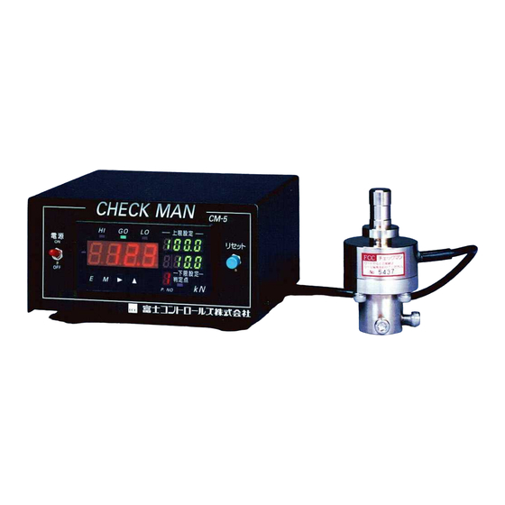
LOAD CHECKING DEVICE
CHECK MAN
Instruction manual
Make sure to read this manual before using this unit. Then,
keep it in a safe location. The specifications of the system may
be changed without prior notice.
Model : C M - 5
(Ver. 4)
FUJI CONTROLS CO., LTD.
1-5-6, Iidabashi, Chiyoda-ku, Tokyo 102-0072
Phone: 03-3265-5437
Fax: 03-3265-5430
Advertisement
Table of Contents

Related Manuals for FUJI CONTROLS CHECK MAN CM-5


Summary of Contents for FUJI CONTROLS CHECK MAN CM-5
- Page 1 Make sure to read this manual before using this unit. Then, keep it in a safe location. The specifications of the system may be changed without prior notice. FUJI CONTROLS CO., LTD. 1-5-6, Iidabashi, Chiyoda-ku, Tokyo 102-0072 Phone: 03-3265-5437 Fax: 03-3265-5430...
- Page 2 Thank you for purchasing our CHECK MAN/CM-5. This instruction manual describes the basic functions and precautions in simple terms, so that even people who are unfamiliar with this system can learn how to use it safely. Before using this unit, read this manual thoroughly in order to get the maximum performance from the CHECK MAN/CM-5.
- Page 3 "Indicator." It will also use the relay contacts to provide an external signal whether the press fitting was good or not. ● The CM-5 can store 8 pairs of upper and lower limit values in memory. To change workpiece types easily, just enter the values for each type before starting the operation.
-
Page 4: Table Of Contents
When opening the shipping package The following items should have been packed in the box. Please open the box as soon as possible and make sure all of the items were packed inside. Make sure there are no missing items. Make sure that none of the items is damaged. -
Page 5: Name And Function Of Each Part On The Measurement Device Housing
Name and function of each part on the measurement device housing 5 2 6 7 3 4 C H E C K MA N CM-5 上限設定 電 源 リ セッ ト 下限設定 判定点 P. NO 1 11 12 13 10... - Page 6 * Load measurement complete signal: After the system receives this signal, it will stop measuring loads and compare the measured value with the preset upper and lower limits. At the same time, the system will let you know the result of the comparison using the display and by outputting a signal on the relay contacts.
- Page 7 Measured load value < Lower limit value At the same time, terminals ⑬ and ⑭ ("a" contacts: normally open) on the terminal block (on the back) will be shorted together until the next reset (start) signal is input or until the system is manually reset.
-
Page 8: Operating Chart
Operating Chart After receiving a reset (start) signal, the CM-5 will measure load values continuously until a load measurement complete signal is received. Then it will compare the results with the user specified limits. Press operation CM signals CM comparison signal output Start one press operation Reset signal cycle... - Page 9 starting a pressing operation. 2. Load measurement complete signal A load measurement complete signal is created when terminals ③ and ④ are opened, ("b" type contact) or the voltage level rises to logical 1. The system responds to the rising edge when the shorted terminals are opened (when the level changes from "0"...
- Page 10 Press output control, such as a caulking operation Position of the press T h e p r e s s The part The press ram Start of T h e p r e s s P r e s s i n g pressing c y c l e i s a press cycle...
-
Page 11: External Connection Terminals And Their Functions
External connection terminals and their functions Terminal block on the back of the measurement device Power supply terminals for Comparison signals sensors HI GO LO 5 VDC Note: Terminals are isolated. 14 10 12 a a a COM COM COM (There is no continuity between these terminals.) 9... - Page 12 CAUTION Terminals ①, ②, ③, ④ and ⑮ must only be connected to a 5 VDC circuit. Be careful not to connect them to 100 VAC. (The internal circuits may catch fire.) ⑤: Manual reset terminal The manual reset terminal is connected to the reset switch on the front side of the measurement device. It is connected internally to terminal ①.
- Page 13 Cycle start Cycle start Press One cycle D o w n Any time before one cycle 10 msec. or more is complete Reset signal O F F Load measurement Make sure it is ON before Make sure it is ON before the reset signal is input the reset signal is input complete signal...
-
Page 14: Connection Examples
Connection examples 1. Reset (start) signal The system uses the movement of the press When using the press ram movement as trigger input signel for this system ram to send the reset (start) signal for the CM-5 measurement device. Connect the micro-switch "b"... - Page 15 3. Load measurement complete signal (Examples for caulking) When using a timer Power supply Shown on the left is an example for checking terminals for Comparison signals sensors a caulking load using the timer "b" contacts Terminal block on the 5VDC measurement device from the press timer for press fitting...
-
Page 16: Connection Procedures
Connection procedures 1. Installing a load cell ① Install the load cell on the shank on the press, or on the center of the jig ( see the dimension drawings on pages 28 and 29). When installing a load cell that was designed to be mounted on the ram shank (003, 03, 10U, 20U), make sure to secure it at two points, so that the diagonally shaded area ( the loaded face) shown in the dimension drawings contacts the press shank properly. -
Page 17: Entering And Changing Each Setting Using The Membrane Switches
Entering and changing each setting using the membrane switches First, enter or change the settings using the double-key function. Use the four membrane keys in the bottom row ( 、 、 ) on the front panel of the CM-5. The items that you can specify (such as the names of data settings) will be displayed in alphabetical order in the "Load lower-limit digital display."... - Page 18 To perform an equal value calibration, you need the latest data for the load cell that you will be using. If your load cell is not new, its actual data characteristics may be different from the initial data characteristics that it had when it was delivered from the factory, depending on its condition and how long it has been used.
-
Page 19: Prohibiting Changes
Prohibiting changes Prohibiting changes: This mode prevents the upper and lower values, and the selected pair of limit values from being changed by pressing the keys. 1. Press the keys. (Press the key, first.) ..During this operation, you cannot measure loads. - Page 20 ③ Display the pair number whose values you want to check. ④ Then, press the key repeatedly to display the limit type in the lower-limit display. The limit types will be displayed in the following order: "( )→( )→( )→( )"...
-
Page 21: Changing And Storing Upper And Lower Comparison Values
Changing and storing upper and lower comparison values You can change the upper and lower values that are used for comparing with the measured load. Up to eight pairs of upper and lower values can be stored in memory. The values in the table below are already stored as default values. - Page 22 4. Press the key. --- Then you can change the value of the 10 digit. key is used to select a different digit place. Press this key once and the decimal point next to the digit will flash. 5. Next, press the key.
- Page 23 10. Press the key. Each time you press the key, the number in the 10 digit location will change in the following order: "0→1→2→3→4→5→6→7→8→9→0" Change this digit to " ." 11. Repeat the operations in steps 8 and 9 on the previous page. Set the values of the 10 and 10 digits to "2"...
-
Page 24: Method For Selecting A Pair Of Upper And Lower Limits
Method for selecting a pair of upper and lower limits This section describes the method for selecting pairs of upper and lower limits when the system is part of an actual production line. (Up to 8 pairs of limits can be stored in memory.) If the mode is set to " "... - Page 25 3. Press the key twice. The lower-limit display will indicate that the frequency can be set, as shown below. Digital load display Lower-limit display " means that you can change the ←" frequency. ↓ " " is the 50 Hz setting. 4.
-
Page 26: Method For Selecting The Measurement Mode
Method for selecting the measurement mode This section describes the method for selecting either one of the measurement modes used to compare the measured load with the upper and the peak value mode* the end value lower limit values. You can select either mode* *... - Page 27 4. Press the key. Each time you press the key, the digital load display will alternate between " " and " ". Select " ." on this display. Digital load display Lower-limit display ↓ " " means that the end measurement mode is selected. 5.
-
Page 28: Maintenance
② If smoke or smells come from the system, turn OFF the power immediately. Then please contact the sales shop or us. FUJI CONTROLS CO., LTD./ Technical Department : ■ Phone: 03-3265-5437 Fax: 03-3265-5430 E-mail: LES07537@nifty.ne.jp... -
Page 29: Troubleshooting
Troubleshooting 1. Load cell If a load exceeding the rated value is imposed on the load cell, or a horizontal load is imposed on it, it will be permanently distorted, and one or more of the symptoms listed below will occur. ●... - Page 30 them back to you. d Display: The digital load display reads " ", the lower-limit display reads " ", and all of the decimal points flash. The pair limit display for the upper and lower limits is "1." Problem: The condition data ( ) that were set with in mode "03", may be corrupt.
-
Page 31: Check Man And Load Cell Specifications
− 27 −... -
Page 32: Measurement Device Dimension Drawings
MEASUREMENT DEVICE DIMENSION DRAWING Power cord (2-prong plug) Metal connector for load cell cable The numbers in parenthese( NOTE : are for the main housing. on the bottom When mounting the main housing by using the (Tapped hole used for mounting the CM-5) tapped holes on the bottom, do not insert screws that go deeper than 10 mm inside the housing. - Page 33 LOAD CELL MEASUREMENT DRAWINGS 0 3 F 1 ( 3 0 k N { 3 , 0 6 0 k g f } ) 0 0 3 F 1 ( 3 k N { 3 0 6 k g f } ) Load surface M6 through-hole Load surface...
-
Page 34: Circuit Examples For Connecting A Timer Box
Circuit examples for connecting a timer box The examples below show circuits for press fitting and caulking operations after the CHECK MAN connected to a pneumatic press, and how to control them using a timer box. CAUKING SPRECIFICATIONS PRESS FITTING SPECIFICATIONS Power Power 1 0 0 V A C...
Need help?
Do you have a question about the CHECK MAN CM-5 and is the answer not in the manual?
Questions and answers
Request quotation, digital load cell meter, model: CM-5