Table of Contents
Advertisement
Quick Links
CE 208
Electric meter
multifunctional single-phase
Body S7
SANT.411152.068-05 OM Operation Manual
OKP 42 2863 6
Harmonized System Codes (TN VED) 9028301 100
Manufacturer:
JSC «Electrotechnical factories «Energomera»
415 Lenin Str., Stavropol, Russia 355029
Tel.: (8652) 35-75-27, Fax: 56-66-90,
Hot line (free): 8-800-200-75-27
e-mail: concern@energomera.ru
www.energomera.ru
Warranty service:
217 Gagarin street, Nevinnomyssk, Stavropol Region,
357106
Advertisement
Table of Contents

Related Manuals for Energomera CE 208


Summary of Contents for Energomera CE 208
- Page 1 Body S7 SANT.411152.068-05 OM Operation Manual OKP 42 2863 6 Harmonized System Codes (TN VED) 9028301 100 Manufacturer: JSC «Electrotechnical factories «Energomera» 415 Lenin Str., Stavropol, Russia 355029 Tel.: (8652) 35-75-27, Fax: 56-66-90, Hot line (free): 8-800-200-75-27 e-mail: concern@energomera.ru www.energomera.ru...
-
Page 3: Table Of Contents
CONTENTS SAFETY REQUIREMENTS ....................................5 METER DESCRIPTION ......................................6 PURPOSE ......................................... 6 THE METER'S FUNCTIONS ARE DESCRIBED IN DETAIL IN THE FULL VERSION OF SANT.411152.068-05 UM USER MANUAL............................................8 Designation of meter modifications ................................8 The meter is certified....................................... 9 Normal usage conditions: ..................................... - Page 4 ROUTINE MAINTENANCE ....................................38 STORAGE AND TRANSPORTATION CONDITIONS ............................ 39 CONTAINERS AND PACKING ................................... 40 LABELING ........................................... 40 ANNEX A ............................................42 ANNEX B ............................................43 ANNEX C ............................................44...
-
Page 5: Safety Requirements
This SANT411152.068-05 OM Operation Manual contains brief information about CE208 S7 multifunctional single-phase electric meter (hereinafter referred to as the "Meter"). Complete information on the above meter is contained in SANT411152.068-05 UM User Manual, which can be found at the manufacturer's website: http://www.energomena.ru/ru/products/meters/ce208-all. -
Page 6: Meter Description
7 MΩ – at an ambient air temperature (40±2) °С, relative air humidity of 93%. The meter must be installed and operated in accordance with the applicable rules for technical operation of electrical installations. Do not put foreign objects on the meter, avoid bumps. 2 METER DESCRIPTION PURPOSE The meter is single-phase, multifunctional, direct connection, and is designed to measure active and reactive... - Page 7 recording the violation of an individual power quality indicator (event logs available for reading on the interface); monitoring active power consumption; monitoring "instantaneous power" consumption; monitoring active energy consumption (control of energy limits, prepaid mode, low consumption control); ...
-
Page 8: The Meter's Functions Are Described In Detail In The Full Version Of Sant.411152.068-05 Um User Manual
THE METER'S FUNCTIONS ARE DESCRIBED IN DETAIL IN THE FULL VERSION OF SANT.411152.068-05 UM USER MANUAL. The meter can be used in Automatic Informational and Measuring Systems for Commercial Electric Power Accounting (AIMS CEPA) to transfer the parameters measured or calculated to the control room for controlling, accounting and distributing electric power. -
Page 9: The Meter Is Certified
Table 2.1 Meter constant Position Nominal, base Meter designation Nominal voltage, V imp./(kW•h), of the decimal (max.) current, A imp./(kVar•h) point CE208 S7.845.X...X; 5 (60) 2000 000000.00 CE208 S7.745.X...X CE208 S7.846.X...X; 5 (100) 2000 000000.00 CE208 S7.746.X...X 2.2.3 Example of a meter record When ordering a meter, the required version is determined by the structure of the designation shown in Figure 2.1. - Page 10 Designation of the integrated communication module Additional functions: See Table 2.3. Integrated communication interfaces: See Table 2.2. Number of measuring elements: - meter with one current sensor (in the phase circuit); - meter with two current sensors (in the phase and neutral circuits);...
- Page 11 Table 2.2 Item No. Designation Interface Optical port А RS485 PLC interface Radio interface with a built-in antenna Radio interface with an external antenna socket GSM/GPRS modem Ethernet interface Table 2.3 Item No. Designation Additional function Tripping relay (load breaker) 2 directions of accounting Network parameters Electronic seals...
-
Page 12: Normal Usage Conditions
Normal usage conditions: - ambient air temperature (23±2) °С; - ambient air relative humidity (30-80) %; - atmospheric pressure from 70 to 106.7 kPa (537...800 mm Hg). - network frequency (50±0.5) Hz; - the shape of the voltage curve of the measuring network is sinusoidal with a nonsinusoidal factor according to EN 50160:2010*. -
Page 13: Ambient Conditions
Ambient conditions 2.6.1 The meter is protected from dust and water. The protection degree of the meter is IP54 according to IEC 529-89. 2.6.2 The meter is resistant against single impacts with a maximum acceleration of 300 m/s 2.6.3 The meter is resistant to vibrations in the frequency range (10-150) Hz. The meter body withstands impact of spring hammer blows with kinetic energy (0.20±0.02) J applied to 2.6.4 the external surfaces of the body, including the windows, and to the lid of the clamps. - Page 14 Table 2.4 Specification name Specification value Note Base (max.) currents 5(60); 5(100); Direct connection Nominal phase voltage 230 V Operating phase voltage (0.55...1.21) U (50±2.5) Hz Nominal network frequency Non-sinusoidal factor of the measuring In accordance with EN 50160:2010 network voltage, %, max Sensitivity threshold 0,002 Ib Number of decimal places on the LCD...
- Page 15 Table 2.4 (continued) Specification name Specification value Note Active power consumed by the built-in For versions with communication communication modules at the nominal modules voltage value, max, W ± 0.5 s/day Limit of the clock basic absolute error Manual and system correction, clock ±...
- Page 16 Table 2.4 (continued) Specification name Specification value Note Number of exclusive days up to 80 Number of daily rate scales up to 32 Number of power control zones in a Number of power control zone up to 12 schedules 1; 2; 3; 4; 5; б; 10; 12; 15; 20, 30, Power averaging time 60 min Number of accounted tariffs by events...
- Page 17 Table 2.4 (continued) Specification name Specification value Note Depth of monthly maximum power storage in the three power control 13 months Current and 12 previous zones Number of parameters in a profile up to 6 Profile storage depth, days With an averaging time of 30 minutes 1;...
- Page 18 Table 2.4 (continued) Specification name Specification value Note Duration of output pulses 35 ms In a TM mode Depending on the characteristics of Interface communication speed From 300 to 19200 Bd communication modules Optical port communication speed From 300 to 19200 Bd Meter update time Reading time of any meter parameter from 0.1 to 1000 s (at 9600 Bd)
-
Page 19: Meter Design
Table 2.4 (continued) Specification name Specification value Note Average service life 30 years Meter cover and terminal block cover Meter cover and terminal cover opening control opening logs Protection against unauthorized access Meter password, hardware lock Meter design The meter design complies with the requirements of EN 50470-1-2015 and the manufacturer's drawings. The meter is made in a plastic body. -
Page 20: Preparing The Meter For Operation
"ACCESS" button are closable with a plastic cover. In order to access the "ACCESS" button (programming permission), you need to remove the sealing label of the energy supplying company that installed the meter. The meter comprises: measuring module; supply module; ... - Page 21 It is not allowed to get a wire with insulation into the clamping area, as well as for the stripped area to protrude outside the block. First, tighten the top screw. Pull the wire lightly to make sure that it has been clamped. Then tighten the bottom screw.
- Page 22 3.4 Wiring diagrams The designation of meter contacts is shown in Figure 3.1 1 - Meter designation. 2 - Indicator. 3 - Network indicator. 4 - Active energy indicator. 5 - Reactive energy indicator. 6 - Communication optical port. SHOT SCROL 7 - "SHOT"...
- Page 23 3.4.1 Pulse output connection The meter features TM1 pulse output. The output may be used (programmed) as the main transmitting output device of active or reactive energy. The output is implemented on transistors with an “open” collector and is intended for switching DC voltage. Nominal supply voltage (10±2) V, maximum allowable value is 24 V. The value of the switched nominal current is (10±1) mA, the maximum allowable value is 30 mA.
- Page 24 9600 Bd, the use of terminal resistors is not recommended 3.4.2.2 Connection of PLC, GSM, Ethernet, radio interfaces The connection of the CE 208 meter to the PC via communication modules is described in detail in SANT.411152.068-05 UM.
- Page 25 To PC RS485 adapter in RS232/USB Note - Stretch resistors (+R) and (-R) (nominal 100 kΩ) are installed in the meter and are always connected to the A and B lines, respectively. When it is necessary to connect external stretch resistors (resistance of 560 Ω), you should: make contact between pin 9 and pin 12, in this case the +R resistor installed in the meter is activated;...
-
Page 26: Lithium Battery Replacement
Lithium battery replacement In the meter, an integrated CR14250BL-VY lithium battery or equivalent is used for the real-time clock. The lithium battery should only be replaced by a service company or in the workshop of the power supplying organization that is authorized to repair and check the meter. In the meter, it is necessary to remove the seals of the power supplying organization, the service department and state verification, remove the meter cover, and remove the top meter board from the connector. -
Page 27: Meter Configuration
Meter configuration Configuration is carried out according to SANT411152.068-05 UM User Manual, which is available at the manufacturer's website: http://www.energomera.ru/ru/products/meters/ce208-all. 4 READING THE METER The meter can be read both manually and in the automated mode. In the automated mode, full information on energy consumption can be obtained using a PC via the interface. - Page 28 Table 4.1 To LCD By interfaces Number of digits Name of output parameters Measurement Measurement Number of digits left/right of the units units left/right of the point point Voltage 4 categories А А Current 4 categories Active power W-kW 4 categories Reactive power Var-kVar 4 categories...
-
Page 29: Viewing Total Accumulated Values (On An Accrual Basis)
Table 4.1 (continued) To LCD By interfaces Number of digits Name of output parameters Measurement Measurement Number of digits left/right of the units units left/right of the point point Averaged power values of the load profiles Viewing total accumulated values (on an accrual basis) The amount of active imported, active exported (only for bi-directional meters), reactive imported and exported energy on an accrual basis, cumulatively and by tariffs is available for viewing on the meter's LCD in the first group parameters. - Page 30 OBIS Code Figure 4.1 — Appearance of the CE208 S7 meter LCD indicator Table 4.2 — OBIS code values for the first group of meter parameters OBIS code value Type of accounted energy Tariff 1.8.0 Active imported Total by tariffs 1-8 1.8.1 Active imported Tariff 1...
- Page 31 Table 4.2 (continued) OBIS code value Type of accounted energy Tariff 1.8.A Active imported Tariff 10 1.8.P Active imported Cumulatively by the phase wire 1.8.n Active imported Cumulatively by the neutral wire 2.8.0 Active exported Cumulatively by all tariffs 2.8.1 Active exported Tariff 1 2.8.2...
- Page 32 Table 4.2 (continued) OBIS code value Type of accounted energy Tariff 2.8.A Active exported Tariff 10 2.8.P Active exported Cumulatively by the phase wire 2.8.П Active exported Cumulatively by the neutral wire 3.8.0 Reactive imported Cumulatively by all tariffs 3.8.1 Reactive imported Tariff 1 3.8.2...
- Page 33 OBIS code value Type of accounted energy Tariff 4.8.0 Reactive exported Cumulatively by all tariffs 4.8.1 Reactive exported Tariff 1 4.8.2 Reactive exported Tariff 2 • • • 4.8.A Reactive exported Tariff 10 4.8.P Reactive exported Cumulatively by the phase wire 4.8.n Reactive exported Cumulatively by the neutral wire...
- Page 34 "А+" → "А-" → "R+" → "R-" By briefly pressing the “VIEW” button, select a tariff: "Total" → "Tariff 1" → "Tariff 2" → "Tariff 10" Figure 4.2 shows the value ("00089.38 kW•h") of the active imported energy on an accrual basis for the fifth tariff (OBIS code value is "1.8.5").
- Page 35 Figure 4.3 shows the value ("00096.89 kVAr•h") of the reactive exported energy on an accrual basis for the third tariff (OBIS code value is "4.8.3"). At the present moment: • the active tariff is 2 ("Т2"); • the current time is "18h58m39s"; •...
- Page 36 "А+, total" → "А+", "Tariff 1" → "А+", "Tariff 2" →...→ "А+→", "Tariff 10" → → "А-", "total" → "А-", "Tariff 1" → "А-', "Tariff 2" →...→ "А-", "Tariff 10" → → "R+", "total" → "R+", "Tariff 1" → "R+", "Tariff 2" →...→ "R+", "Tariff 10" → "R-", "total" → "R-", "Tariff 1"...
-
Page 37: Meter Verification
5 METER VERIFICATION The verification is carried out according to “CE208 multifunctional single-phase electric meters. SANT41 1152.068 D1 verification method”, when released from production, after mid-term repair or periodically once every years. 6 MAINTENANCE AND SEALING Maintenance of the meter at the installation sites consists in systematic monitoring of its operation and eliminating meter errors and malfunctions. -
Page 38: Routine Maintenance
7 ROUTINE MAINTENANCE Possible malfunctions and methods for their elimination by the consumer are given in Table 7.1. Table 7.1 Name and signs of the malfunction Possible cause Elimination method No voltage at the meter voltage Check for voltage at the meter's terminals 1 The LCD is off voltage terminals... -
Page 39: Storage And Transportation Conditions
Table 7.1 (continued) Name and signs of the malfunction Possible cause Elimination method Wrong connection Connect the telemetry lines in of telemetry lines to the meter's 5 Missing or poor power accounting accordance with the OM terminals via telemetry channels Configure the telemetry outputs 2 The telemetry outputs are poorly correctly... -
Page 40: Containers And Packing
9 CONTAINERS AND PACKING The meters, operational and shipping documentation are packed in accordance with the manufacturer's drawings. When prepared for packaging, the meter is placed in a plastic bag. Operational documentation is in consumer packaging on top of the product. The consumer packaging is covered with packing tape. - Page 41 - the number of phases and the number of wires in the circuit for which the counter is intended, as a graphic symbol in accordance with GOST 25372-95; -- trademark of the manufacturing enterprise ENERGOMERA®; EN 50470-1-2015, EN 50470-3:2006, IEC62053-23:2003;...
-
Page 42: Annex A
ANNEX A (required) The permissible error limits of the measured values A.1 The limits of the permissible basic relative error when measuring the root-mean-square values of current δ, in percent, do not exceed the values shown in Table A.1. Table А.1 Limits of permissible basic error δ... -
Page 43: Annex B
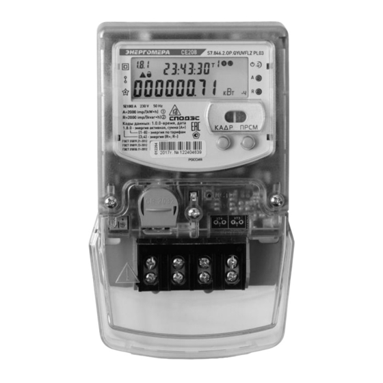
ANNEX B (required) CE208 S7 meter general appearance... -
Page 44: Annex C
ANNEX C (required) CE208 S7 meter connection diagram L to LOAD N to load... - Page 48 Rev. 1 28.11.18...
Need help?
Do you have a question about the CE 208 and is the answer not in the manual?
Questions and answers