Table of Contents
Advertisement
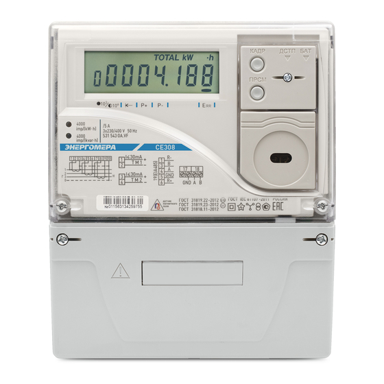
СЕ308
Electric energy meter
Three-phase multifunctional
Case type S31, S34
САНТ.411152.107-05.1 РЭ
Operation Manual
OKP 42 2863 6
Harmonized System Codes (TN VED) 9028301 100
Manufacturer:
Electrotechnical Factories Energomera JSC
415 Lenina Str., Stavropol, Russia 355029
Tel.: (8652) 35-75-27, Fax: 56-66-90,
Hot line (free): 8-800-200-75-27
e-mail: concern@energomera.ru
www.energomera.ru
Warranty service:
217 Gagarina street, Nevinnomyssk,
Stavropol region, 357106
Advertisement
Table of Contents

Related Manuals for Energomera CE308


Summary of Contents for Energomera CE308
- Page 1 Case type S31, S34 САНТ.411152.107-05.1 РЭ Operation Manual OKP 42 2863 6 Harmonized System Codes (TN VED) 9028301 100 Manufacturer: Electrotechnical Factories Energomera JSC 415 Lenina Str., Stavropol, Russia 355029 Tel.: (8652) 35-75-27, Fax: 56-66-90, Hot line (free): 8-800-200-75-27 e-mail: concern@energomera.ru www.energomera.ru...
-
Page 3: Table Of Contents
CONTENTS 1 SAFETY REQUIREMENTS ...........................5 2 METER DESCRIPTION ............................6 2.1 Purpose ................................6 2.2 Designation of meter modifications ........................9 2.3 Certification Information ...........................11 2.4 Normal usage conditions: ..........................12 2.5 Operating usage conditions ..........................12 2.6 Ambient conditions ............................13 2.7 Technical specifications .............................13 2.8 Meter design ..............................19 3 PREPARING THE METER FOR OPERATION....................... - Page 4 6 MAINTENANCE AND SEALING........................46 7 ROUTINE MAINTENANCE ..........................47 8 STORAGE AND TRANSPORTATION CONDITIONS .................... 48 9 CONTAINERS AND PACKING .......................... 48 10 LABELING ..............................49 ANNEX A ................................51 ANNEX B ................................52 ANNEX C ................................54...
-
Page 5: Safety Requirements
This САНТ.411152.107-05.1 РЭ (Operation Manual) contains brief information on CE308 S31, CE308 S34 multifunctional three-phase electric meter (hereinafter referred to as the «Meter»). Complete information on the above meter is contained in САНТ.411152.107-05.1 РП (User Manual), which can be found at the manufacturer’s website: www.energomera.ru/ru/products/meters/ce308-all... -
Page 6: Meter Description
1.5 Insulation resistance between the casing and electrical circuits, at least: 20 MΩ — under conditions of clause 2.5; 7 MΩ – at an ambient air temperature (40±2) °С, relative air humidity of 93%. 1.6 The meter must be installed and operated in accordance with the applicable rules for technical operation of electrical installations. - Page 7 • recording the violation of an individual power quality indicator (event logs available for reading on the interface); • monitoring active power consumption; • monitoring «instantaneous power» consumption; • monitoring active energy consumption (control of energy limits, prepaid mode, low consumption control); •...
- Page 8 manual САНТ.411152.107-05.1 РП; • mechanism for flexible adjustment of the reaction to events occurring in the meter; • DLMS/COSEM exchange protocol support; • display of information on the LCD accompanied by OBIS codes; • IEC 60870-5-104-2004 exchange protocol support; • management of consumer load according to a predefined schedule. A detailed description of meter functions is given in the full version of САНТ.411152.107-05.1 РП...
-
Page 9: Designation Of Meter Modifications
2.2 Designation of meter modifications 2.2.1 The structure of meter designation is shown in Fig. 1. СЕ308 XX.ХXХ.XХ.XXX XXXX Designation of the integrated communication module Additional functions: See Table 2.1. Integrated communication interfaces: See Table 2.1. Nominal or base (max.) current: 3 –... - Page 10 Table 2.1 Additional software and hardware Designation Interface Designation options Optical interface (OI) Alarm relay M-BUS Load control relay RS232 2 metering directions RS485 External display Power quality parameters Electronic seals Optional connection of a backup Ethernet power source LCD backlighting Radio interface with a built-in antenna Magnetic field sensor...
-
Page 11: Certification Information
100 A (6), with an optical port (O), with an RS485 interface (A), with an alarm relay (S), for two measuring directions (Y), measuring power quality parameters (U), with a lid opening control (V), with an indicator light (L), with a magnetic field sensor (F) and an extended set of parameters (Z): «CE308 S31.746.OA.SYUVLFZ multifunctional three-phase electric meter, TУ 4228-104-78189955-2014». -
Page 12: Normal Usage Conditions
2.4 Normal usage conditions: – ambient air temperature (23±2) °С; – ambient air relative humidity (30-80) %; – atmospheric pressure from 70 to 106.7 kPa (537...800 mm Hg). – network frequency (50±0.5) Hz; – the shape of the voltage curve of the measuring network is sinusoidal with a nonsinusoidal factor according to GOST EN50160:2010*. -
Page 13: Ambient Conditions
2.6 Ambient conditions 2.6.1 In terms of resistance to climatic influences, the meter belongs to group 4 in accordance with GOST 22261-94, with an extended range of temperature and humidity, satisfying version T category 3 in accordance with GOST 15150-69. In terms of resistance to mechanical impacts, the meter belongs to group 2 according to GOST 22261-94. - Page 14 Table 2.3 Specification name Specification value Note Nominal (max.) currents 5(10) А Transformer connection Base (max.) currents 5(60); 5(100) Direct connection 57.7 V; 230 V Transformer connection Nominal phase voltage 230 V Direct connection * — for meters with 57.7 V Operating phase voltage (0.6 (0.75)*...1.21) U nominal voltage...
- Page 15 Table 2.3 (continued) Specification name Specification value Note Total (active) power (consumed by each voltage circuit at nominal voltage, 9(V•A) (0.8 W) Transformer connection Active power consumption at nominal voltage of communication modules, max Limit of the clock basic absolute error ±0.5 s/day Transformer connection Manual and system correction,...
- Page 16 Table 2.3 (continued) Specification name Specification value Note Number of tariff zones in a day up to 16 Number of seasonal schedules in a year up to 12 Number of exclusive days up to 80 Number of daily rate scales up to 32 Number of power control zones in a day...
- Page 17 Table 2.3 (continued) Specification name Specification value Note Depth of monthly maximum power 13 months Current and 12 previous storage in the three control zones Number of parameters in a profile up to 6 With an averaging time Profile storage depth, days of 60 minutes 1;...
- Page 18 Note Meter update time From the moment the voltage is Initial start, max applied Meter weight, max 3 kg for CE308 S31, S34 72х175х215 for CE308 S31 Overall dimensions (height; width; length), max, mm 85х175х280 for CE308 S34 Mean time to failure...
-
Page 19: Meter Design
Specification name Specification value Note Permissible value of switching current on the contacts of the alarm relay (ver- 2 А CE308 S31 sion S), max Permissible switching voltage on the load control relay contacts (version 265 V AC; CE308 S34... -
Page 20: Preparing The Meter For Operation
The terminals for connecting the meter to the network, to interface lines and to pulse outputs are closed with a transparent terminal cover. 3 PREPARING THE METER FOR OPERATION 3.1 Unpacking 3.1.1 After unpacking, inspect the meter visually, verify that there are no mechanical damages, and check the presence and integrity of the seals. -
Page 21: Wiring Diagrams
Таблица 3.1 Meter with a current range The length of the stripped wire, mm Wire cross-section diameter , mm 5(10) А (1÷6) 5(60) А (1÷7) 5(100) А (1÷8) If it is necessary to incorporate the meter into an AMI system, connect the signal wires to the interface outputs in accordance with the wiring diagram. - Page 22 SIM card connector pins 1, 2 – connection of TM1 pulse outputs; pins 3, 4 — connection of TM2 pulse outputs; pins 7, 8 — alarm relay pins (AR); 10 – terminal cover electronic seal microswitch; pin 11 – RS485 interface contact (A’) (in the meter versions with two additional interfaces); pin 12 –...
- Page 23 A, middle B, right GND; pins 19 — depending on the meter version: socket of the built-in Ethernet module; HF – connector for connecting an external antenna; plug. Figure a) first variant of CE308 S31, S34 meter pins designation...
- Page 24 SIM card connector SIM card connector...
- Page 25 A, middle B, right GND; pin 19 – depending on the meter version: socket of the built-in Ethernet module; HF – connector for connecting an external antenna; plug. b) second variant of CE308 S31, S34 meter pins designation Figure 3.1 – СЕ308 pins designation...
- Page 26 – designation of CE308 S31 5X3 meter terminal pins b) – designation of CE308 S31 745 meter terminal pins...
- Page 27 – designation of CE308 S31 746 meter terminal pins d) – designation of CE308 S34 meter terminal pins...
- Page 28 – designation of CE308 S34 meter terminal pins with an adapter for connecting a second zero pin Figure 3.2 – Designation of CE308 meter pins Supplied with the CE308 S34 meter...
- Page 29 3.4.1 Pulse outputs connection The meter has ТМ1 and ТМ2 pulse outputs. The outputs can be used as the main output transmitter with parameters in accordance with IEC 62052-11:2003, IEC 62053-21:2003 (IEC 62053-22:2003). The outputs are implemented on transistors with an «open» collector and are intended for switching DC voltage. Nominal supply voltage (10±2) V, maximum allowable value is 24 V.
- Page 30 Figure 3.4 – Alarm relay connection diagram The CE308 S34 meter load control relay provides a break or connection between pins 1 and 3 for phase A, 4 and 6 for phase B, 7 and 9 for phase C (see Figure 3.2d).
- Page 31 3.4.3 Backup power source (BPS) connection diagram Backup power source connection diagram (only for meter versions CE308 S31, СЕ308 S34 with J). =9-24 V, I =800-300 mA (depending on the U power power power Figure 3.5 – BPS connection diagram 3.4.4 Connection of meter interfaces...
- Page 32 17 (right) and 13 (for CE308 S31, S34) to the zero potential point, otherwise take potential equalization measures. In the event that the length of the communication lines does not exceed several meters and there are no sources of interference, then the connection diagram can be significantly simplified by connecting the meter to the DCU or PC using only two signal wires A and B.
- Page 33 R – termination resistor with a nominal value equal to the cable impedance. GND and GND’ circuits for meters in S3x bodies are used as required. Figure 3.6 – Connection diagram of the CE308 meter with a RS485 interface via RS485/RS232, RS485/USB external adapter to a PC 3.4.4.2 PLC interface connection...
- Page 34 of the meter are connected from the phase C output (output 8) and neutral (outputs 10, 11) (for details, see САНТ.411152.107-05.1 РП). 3.4.4.3 GSM interface connection For meter versions with a built-in GSM interface (versions with G), install a SIM card with a positive balance and a connected data transmission service in the slot and connect a remote antenna to connector 19 (see Figure 3.1b).
-
Page 35: Lithium Cell Replacement
3.5 Lithium cell replacement In the meter, an integrated CR14250BL-VY lithium cell or equivalent is used for the real-time clock. The lithium cell should only be replaced by a service company or in the workshop of the power supplying organization that is authorized to repair and check the meter. In the meter, it is necessary to remove the seals of the power supplying organization, the service department and state verification, remove the meter cover, and remove the top meter board from the connector. -
Page 36: Meter Configuration
3.6 Meter configuration Configuration is carried out according to the САНТ.411152.107-05.1 РП, which is available at the manufacturer’s website www.energomera.ru/ru/products/meters/ce308-all 4 READING THE METER The meter can be read both manually and in the automated mode. In the automated mode, full information on energy consumption can be obtained using a PC or AMI system via the interface (see САНТ.411152.107-05.1 РП). - Page 37 Table 4.1 Counting mechanism and Power transformation ratio Display window display window position 54321.123 kW•h up to 10 10987654321.12345 10987654321.12345 654321.12 kW•h from 10 to 100 10987654321.12345 7654321.1 kW•h from 100 to 1000 10987654321.12345 87654.321 MW•h from 1000 to 10000 10987654321.12345 987654.32 MW•h from 10000 to 100000...
- Page 38 Table 4.2 To LCD By interfaces Name of output Number of Number of digits Measurement Measurement parameters digits left/right left/right of the units units of the point point Voltage 4 digits Current А 4 digits А Active power W-kW 4 digits Reactive power Var-kVar 4 digits...
-
Page 39: Viewing Total Accumulated Values (On An Accrual Basis)
Table 4.3. OBIS code Figure 4.1 — Appearance of the CE308 meter LCD indicator The information displayed by the meter on the LCD is organized in parameter groups. Detailed information on each group is provided in the САНТ.411152.107-05.1 РП. - Page 40 Table 4.3 – OBIS code values for the first group of meter parameters OBIS code value Type of accounted energy Tariff 1.8.0 Active imported Total by tariffs 1-8 1.8.1 Active imported Tariff 1 1.8.2 Active imported Tariff 2 • • •...
- Page 41 Table 4.3 (continued) OBIS code value Type of accounted energy Tariff 2.8.10 Active exported Tariff 10 22.8.0 Active exported Phase 1 (L1) 42.8.0 Active exported Phase 2 (L2) 62.8.0 Active exported Phase 3 (L3) 3.8.0 Reactive imported Total by tariffs 1-8 3.8.1 Reactive imported Tariff 1...
- Page 42 Table 4.3 (continued) OBIS code value Type of accounted energy Tariff 4.8.0 Reactive exported Total by tariffs 1-8 4.8.1 Reactive exported Tariff 1 4.8.2 Reactive exported Tariff 2 • • • • • • • • • 4.8.10 Reactive exported Tariff 10 24.8.0 Reactive exported...
- Page 43 By briefly pressing the «FRAME» button, select the type of metered energy: «A+» → «A-» → «R+» → «R-» By briefly pressing the «VIEW» button, select a tariff: «Total (by tariffs 1-8)» → «Tariff 1» → «Tariff 2» → … …→...
- Page 44 Figure 4.3 shows the value («00096.89 kVAr•h») of the reactive exported energy on an accrual basis for the fifth tariff (OBIS code value is «4.8.3»). At the present moment: • the active tariff is 3 («Т3»); • the current time is «18h58m39s»; •...
- Page 45 «А+, total» → «А+», «Tariff 1» → «А+», «Tariff 2» →...→ «А+→», «Tariff 10» → → «А-», «total» → «А-», «Tariff 1» → «А-», «Tariff 2» →...→ «А-», «Tariff 10» → → «R+», «total» → «R+», «Tariff 1» → «R+», «Tariff 2» →...→ «R+», «Tariff 10» → «R-», «total»...
-
Page 46: Meter Verification
5 METER VERIFICATION 5.1 The verification is carried out according to «CE308 multifunctional three-phase electric meters. САНТ.411152.107 Д1 verification method», when released from production, after mid-term repair or periodically once every 16 years. 6 MAINTENANCE AND SEALING 6.1 Maintenance of the meter at the installation sites consists in systematic monitoring of its operation and eliminating meter errors and malfunctions. -
Page 47: Routine Maintenance
7 ROUTINE MAINTENANCE 7.1 Possible malfunctions and methods for their elimination by the consumer are given in Table 7.1 Table 7.1 Name and signs of the Possible cause Elimination method malfunction 1 Check for voltage at the 1 No voltage at the meter voltage 1 The LCD is off terminals meter’s voltage terminals... -
Page 48: Storage And Transportation Conditions
8 STORAGE AND TRANSPORTATION CONDITIONS 8.1 Meters must be stored in the manufacturer’s packaging at an ambient temperature of 5 to 40 °C and a relative humidity of 80% at a temperature of 25 °C. 8.2 Meters are transported in closed vehicles of any kind. Limiting transportation conditions: –... -
Page 49: Labeling
– the number of phases and the number of wires in the circuit for which the counter is intended, as a graphic symbol in accordance with GOST 25372-95; – trademark of the manufacturing enterprise – ENERGOMERA; – IEC 62052-11:2003, IEC 62053-21:2003(IEC 62053-22:2003), IEC 62053-23:2003. - Page 50 – labeling of controls «FRAME», «VIEW», «ACCESS». There is a place on the cover of the meter’s clamping block for applying the transformation ratio of the measuring current and voltage transformers designed to work in conjunction with the meters, the transformer multiplier and number.
-
Page 51: Annex A
ANNEX A (required) The permissible error limits of the measured values A.1 The limits of the permissible basic relative error when measuring the root-mean-square values of current δ, in percent, do not exceed the values shown in Table A.1. Table А.1 Limits of permissible basic error δ... -
Page 52: Annex B
ANNEX B (required) General appearance of a CE308 S31 meter... - Page 53 General appearance of a CE308 S34 meter...
-
Page 54: Annex C
ANNEX C (required) CE308 230 V 5(10) А meter connection diagram Connection via three current transformers (three-phase four-wire network) 4 5 6 7 8 9 10 Phase А Phase В Load Phase С Neutral... - Page 55 CE308 57.7 V 5(10) А meter connection diagram Connection via three current transformers and three voltage transformers (three-phase three-wire network) 4 5 6 7 8 9 10 Phase А Load Phase В Phase С...
- Page 56 CE308 230 V 5(60) А, 5(100) А meter connection diagram Direct connection (three-phase four-wire network) 9 10 11 А Phase В Phase Load С Phase Neutral...
Need help?
Do you have a question about the CE308 and is the answer not in the manual?
Questions and answers
Здравствуйте. Имеется ли техническая возможность у сетевой организации после перепрограммирования часов счетчика СЕ 308 обнулить показания счетчика?