Table of Contents
Advertisement
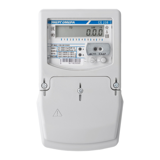
СЕ208
Electric energy meter
Single-phase multifunctional
Case type S7
САНТ.411152.068-05.1 РЭ
Operation Manual
OKP 42 2863 6
Harmonized System Codes (TN VED) 9028301 100
Manufacturer:
Electrotechnical Factories Energomera JSC
415 Lenina Str., Stavropol, Russia 355029
Tel.: (8652) 35-75-27, Fax: 56-66-90,
Hot line (free): 8-800-200-75-27
e-mail: concern@energomera.ru
www.energomera.ru
Warranty service:
217 Gagarina street, Nevinnomyssk,
Stavropol region, 357106
Advertisement
Table of Contents

Related Manuals for Energomera CE208


Summary of Contents for Energomera CE208
- Page 1 Case type S7 САНТ.411152.068-05.1 РЭ Operation Manual OKP 42 2863 6 Harmonized System Codes (TN VED) 9028301 100 Manufacturer: Electrotechnical Factories Energomera JSC 415 Lenina Str., Stavropol, Russia 355029 Tel.: (8652) 35-75-27, Fax: 56-66-90, Hot line (free): 8-800-200-75-27 e-mail: concern@energomera.ru www.energomera.ru...
-
Page 3: Table Of Contents
CONTENTS 1 SAFETY REQUIREMENTS ............................5 2.1 Purpose ................................6 2.2 Designation of meter modifications ........................8 2.3 The meter is certified............................12 2.4 Normal operating conditions: ..........................12 2.5 Operating usage conditions ..........................12 2.6 Ambient conditions ............................13 2.7 Technical specifications ............................. 13 2.8 Meter design .............................. - Page 4 7 ROUTINE MAINTENANCE ..........................36 8 STORAGE AND TRANSPORTATION CONDITIONS ..................... 37 9 CONTAINERS AND PACKING ........................... 38 10 LABELING ..............................39 ANNEX A ................................40 ANNEX B ................................41 ANNEX C ................................42...
-
Page 5: Safety Requirements
This САНТ.411152.068-05.1 РЭ Operation Manual contains brief information about CE208 S7 multifunctional single-phase electric energy meter (hereinafter referred to as the «Meter»). Complete information on the above meter is contained in САНТ.411152.068-05.1 РП User Manual, which can be found at the manufacturer’s website: www.energomena.ru/ru/products/meters/ce208-all. -
Page 6: Purpose
2 METER DESCRIPTION 2.1 Purpose The meter is single-phase, multifunctional, direct connection, and is designed to measure active and reactive electric energy in single-phase AC circuits. The meter has the following functions: • multi-tariff electricity metering (with three tariff levels - event-based, external and time-based tariffing); •... - Page 7 • telemetric output with the ability to use it as a «relay»; • alarm using the interface (the ability to act as an initiator of communication with the level of DCU or HES during: terminal cover opening; exposure to a magnetic field; reparameterization; maximum power excess; deviation from the normalized value of voltage level, etc., in accordance with the full list, for details, see the user manual САНТ.411152.068-05.1 РП);...
-
Page 8: Designation Of Meter Modifications
on a liquid crystal display (LCD) and can be transmitted via an optical port or one of the interfaces. The meter has an electronic measuring mechanism performing active and reactive energy measurement in kW•h and kVar•h, respectively, cumulatively and according to eight tariffs in one or two (for a bi-directional meter) directions of electric energy metering. - Page 9 СЕ 208 S7.Х4Х.Х.OХ.XXXX XXX Designation of the integrated communication module Additional functions: See Table 2.3. Integrated communication interfaces: See Table 2.2. Number of measuring elements: 1 – meter with one current sensor (in the phase circuit); 2 – meter with two current sensors (in the phase and neutral circuits); Nominal or base (max.) current: 5 –...
- Page 10 Table 2.1 Item No. Designation Interface Optical port А RS485 PLC interface Radio interface with a built-in antenna Radio interface with an external antenna socket GSM/GPRS modem Ethernet interface Table 2.2 Item No. Designation Additional function Load control relay 2 directions of metering Network parameters Electronic seals Magnetic field sensor...
- Page 11 (Y), measuring power quality parameters (U), with a cover opening control (V), with a magnetic field sensor (F), with an indicator backlight (L) and an extended set of parameters (Z): Multifunctional single-phase electric meter CE208 S7.845.2.OA.QYUVFLZ ТУ 4228-090-63919543-2012.
-
Page 12: The Meter Is Certified
2.3 The meter is certified The information on meter certification is given in the САНТ.411152.068-03.1 ФО Data Sheet 2.4 Normal operating conditions: – ambient air temperature (23±2)°С; – ambient air relative humidity (30-80)%; – atmospheric pressure from 70 to 106.7 kPa (537-800 mm Hg). –... -
Page 13: Ambient Conditions
2.6 Ambient conditions 2.6.1 In terms of resistance to climatic influences, the meter belongs to group 4 in accordance with GOST 22261-94, with an extended range of temperature and humidity, satisfying version T category 3 in accordance with GOST 15150-69. In terms of resistance to mechanical impacts, the meter belongs to group 2 according to GOST 22261-94. - Page 14 Table 2.4 Specification name Specification value Note Base (max.) currents 5(60); 5(100) А Direct connection Nominal phase voltage 230 V Operating phase voltage (0.55...1.21) U Nominal network frequency (50±2.5) Hz Non-sinusoidal factor of the measuring In accordance with – network voltage, %, max EN50160:2010 Sensitivity threshold 0,002 Ib...
- Page 15 Table 2.4 (continued) Specification name Specification value Note ± 0.15 s/°С per day From minus 10 to 45 °С Limit of the clock additional From minus 40 to minus 10 °С temperature error ± 0.2 s/°C per day and from 45 to 70 °С Duration of data storage when 30 years power is off...
- Page 16 Table 2.4 (continued) Specification name Specification value Note Number of accounted tariffs by events Tariffs 9 and 10 Depth of monthly energy storage at least 40 months Current and 39 previous by tariffs Depth of daily energy storage, 128 days Current and 127 previous accumulated by tariffs Depth of annual energy storage,...
- Page 17 Table 2.4 (continued) Specification name Specification value Note Nominal (permissible) voltage of 10 (24) V DC voltage electrical pulse outputs, max Nominal (permissible) current value of 10 (30) mA DC voltage electrical pulse outputs, max Duration of output pulses 35 ms In a TM mode Depending on the Interface communication speed...
-
Page 18: Meter Design
Table 2.4 (continued) Specification name Specification value Note Average service life 30 years Meter cover and terminal block cover Meter cover and terminal opening control cover opening logs Meter password, Protection against unauthorized access hardware lock Maximum relay current during the turn- 1.1·Imax А... -
Page 19: Preparing The Meter For Operation
• optical port elements; • «FRAME» and «VIEW» buttons; The clamps for connecting the meter to the network, to interface lines and to pulse outputs, «ACCESS» button are closable with a plastic cover. In order to access the «ACCESS» button (programming permission), you need to remove the sealing label of the energy supplying company that installed the meter. -
Page 20: Installation Procedure
3.3 Installation procedure 3.3.1 Connect the electric meter to a single-phase AC network with a nominal voltage of 230 V. To do this, remove the terminal cover and connect the wires by securing them in the terminals of the block according to the wiring diagram printed on the cover, or given in Annex C. -
Page 21: Wiring Diagrams
10* – RS485 interface «B» contact; pin 11* – RS485 interface «-» power supply; pin 12* – RS485 interface «+» power supply. * – only for modifications with an RS485 interface Figure 3.1 – Designation of CE208 S7 meter pins... - Page 22 designation of pins of the meter with RS485 interface designation of pins of the meter with radio modules, with external antenna designation of pins of the meter with Ethernet module designation of pins of the meter with GSM module...
- Page 23 3.4.1 Pulse output connection The meter features TM1 pulse output. The output may be used (programmed) as the main transmitting output device of active or reactive energy, with parameters according to IEC 62052-11:2003, IEC 62053-21:2003 and IEC 62053-23:2003. The output is implemented on transistors with an “open” collector and is intended for switching DC voltage.
- Page 24 9600 bd, the use of termination resistors is not recommended 3.4.2.2 Connection of PLC, GSM, Ethernet, radio interfaces The connection of the CE208 meter to the PC via communication modules is described in detail in САНТ.411152.068-05.1 РП.
- Page 25 R – termination resistor with a rating equal to the cable wave impedance Figure 3.3 – CE208 S7 meter connection diagram with an RS485 interface using an external adapter RS485/RS232, RS485/USB to the PC Note – Biasing resistors (+R) and (-R) (nominal 100 kΩ) are installed in the meter and are always connected to the A and B lines, respectively.
-
Page 26: Lithium Cell Replacement
3.5 Lithium cell replacement In the meter, an integrated CR14250BL-VY lithium cell or equivalent is used for the real-time clock. The lithium cell should only be replaced by a service company or in the workshop of the utility or organization that is authorized to repair and check the meter. -
Page 27: Meter Configuration
3.6 Meter configuration Configuration is carried out according to САНТ.411152.068-05.1 РП, which is available at the manufacturer’s website: www.energomera.ru/ru/products/meters/ce208-all. 4 READING THE METER The meter can be read both manually and in the automated mode. In the automated mode, full information on energy consumption can be obtained using a PC or AMI system via the interface. - Page 28 Table 4.1 To LCD By interfaces Name of output parameters Measure- Number of dig- Measure- Number of digits ment its left/right of ment left/right of the units the point units point Voltage 4 digits Current А 4 digits А Active power W-kW 4 digits Reactive power...
-
Page 29: Viewing Total Accumulated Values (On An Accrual Basis)
In this case, «N» symbol will be displayed on the LCD. OBIS code Figure 4.1 — Appearance of the CE208 S7 meter LCD indicator... - Page 30 Table 4.2 – OBIS code values for the first group of meter parameters OBIS code value Type of accounted energy Tariff 1.8.0 Active imported Total by tariffs 1-8 1.8.1 Active imported Tariff 1 1.8.2 Active imported Tariff 2 • • •...
- Page 31 Table 4.2 (continued) OBIS code value Type of accounted energy Tariff 2.8.A Active exported Tariff 10 2.8.P Active exported Cumulatively by the phase wire 2.8.n Active exported Cumulatively by the neutral wire 3.8.0 Reactive imported Cumulatively by all tariffs 3.8.1 Reactive imported Tariff 1 3.8.2...
- Page 32 Table 4.2 (continued) OBIS code value Type of accounted energy Tariff • • • 4.8.A Reactive exported Tariff 10 4.8.P Reactive exported Cumulatively by the phase wire 4.8.n Reactive exported Cumulatively by the neutral wire 4.2.1 Viewing total accumulations when the meter is powered from the network Go to the first group of meter parameters.
- Page 33 Figure 4.2 shows the value («00089.38 kW•h») of the active imported energy on an accrual basis for the fifth tariff (OBIS code value is «1.8.5»). At the present moment: • the active tariff is 5 («Т5»); • the current time is «09h08m06s»; •...
- Page 34 Figure 4.3 – Reactive exported energy on an accrual basis for the third tariff 4.2.2 Viewing the total accumulations of a de-energized meter (when powered by the built-in lithium cell). Press the «FRAME» button briefly. On the LCD screen, the first frame of the viewed «GROUP 1» group parameters will be displayed, containing information on the amount of consumed active energy, cumulatively, by all tariffs (OBIS code value is «1.8.0»).
-
Page 35: Meter Verification
LCD. For details on masking, see САНТ.411152.068-05.1 РП. 5 METER VERIFICATION 5.1 The verification is carried out according to «CE208 multifunctional single-phase electric meters. САНТ.411152.068 Д1 verification method», when released from production, after mid-term repair or periodically once every 16 years. -
Page 36: Maintenance And Sealing
6 MAINTENANCE AND SEALING 6.1 Maintenance of the meter at the installation sites consists in systematic monitoring of its operation and eliminating meter errors and malfunctions. ATTENTION! IN CASE OF LCD FAILURE, THE INFORMATION IS STORED FOR 30 YEARS. YOU CAN READ THE INFORMATION VIA THE METER INTERFACE BY CONNECTING THE METER TO THE POWER NETWORK. -
Page 37: Storage And Transportation Conditions
Table 7.1 (continued) Name and signs of the Possible cause Elimination method malfunction 2 The information displayed on the 1 Failure in the meter's electronic LCD is not changing, no reaction 1 Send the meter to repairs circuit to the buttons 3 When a load is connected to the meter, the measuring direction 1 Incorrect connection of parallel... -
Page 38: Containers And Packing
8.2 Meters are transported in closed vehicles of any kind. Limiting transportation conditions: – ambient air temperature from minus 40 to plus 70 °С. – relative humidity 98% at a temperature of 35 °С. – atmospheric pressure from 70 to 106.7 kPa (537...800 mm Hg). –... -
Page 39: Labeling
10.1 Information applied to the front panel of the meter by offset printing or in another way not degrading the quality: – meter type designation — CE208; – accuracy class according to IEC 62052-11:2003, IEC 62053-21:2003 and IEC 62053-23:2003; – meter constant in accordance with Table 2.3;... -
Page 40: Annex A
ANNEX A (required) The permissible error limits of the measured values A.1 The limits of the permissible basic relative error when measuring the root-mean-square values of current δ in percent, do not exceed the values shown in Table A.1. Table А.1 Limits of permissible basic error δ... -
Page 41: Annex B
ANNEX B (required) CE208 S7 meter general appearance... -
Page 42: Annex C
ANNEX C (required) CE208 S7 meter connection diagram...
Need help?
Do you have a question about the CE208 and is the answer not in the manual?
Questions and answers
Как снимать показания пульт CE 208
To read the readings from the Energomera CE208 remotely, connect the meter to the power network and access the data through the meter interface. If the LCD fails, information is still stored for 30 years and can be read via the interface. Remote reading may use the RS485 interface, if available on the meter version.
This answer is automatically generated