Table of Contents
Advertisement
Quick Links
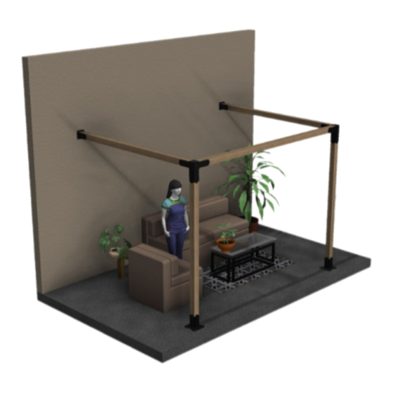
4x4 Surface Mount Wall Mount Single Cubic Pergola Kit
WARNING: If the information in these instructions is not followed exactly, weakening or failure of the erected
structure may result causing property damage, personal injury, or loss of life.
All brackets designed and sold by RioOutdoors.com are to be used for building pergolas only and are not to be used for
other structure construction purposes.
Figure 1: Items included in the kit, (
Items not included in this kit: wood, tools, some hardware.
1 |
P a g e
Installation Instructions
4S-WSC
Pergola Kits
).
������������������������ ���� �������� ���� ����
������������������������ ���� ����
•
Thoughtfully engineered
Brackets eliminate all wood-
joinery skills requirements.
•
Skills required: drill holes
in concrete and hammer
in anchors, drilling pilot
holes and driving lag
screws into lumber.
•
Easy lift and place U-
channels eliminate need
for lifting equipment.
Super-easy assembly
work.
•
Self-aligning design
squares up structure
automatically.
•
Estimated Assembly
Time is less than 1-hour.
Advertisement
Table of Contents

Related Manuals for RioOutdoors 4S-WSC


Summary of Contents for RioOutdoors 4S-WSC
- Page 1 WARNING: If the information in these instructions is not followed exactly, weakening or failure of the erected structure may result causing property damage, personal injury, or loss of life. All brackets designed and sold by RioOutdoors.com are to be used for building pergolas only and are not to be used for other structure construction purposes.
-
Page 2: Table Of Contents
A properly sized pilot hole must be drilled before you attempt to drive lag screws into any pergola lumber member. See Table, below. Driving lag screws into lumber, without first drilling a pilot hole, can prevent the lag screw from driving fully into the wood or can lead to crack formation while driving the lag screw in, or later, as the wood dries naturally. -
Page 3: Safety And Warning Information
GENERAL INFORMATION 1.1 SAFETY AND WARNING INFORMATION 1.1.1 Building Permit & Inspection Requirements We recommend that you consult with your local building permit office and obtain advice and any required building permits and inspection approvals from the local building inspection department or the local authority over building codes. 1.1.2 Other Cautions CAUTION: Adhere to all safety requirements. -
Page 4: Tools Required
1.2 TOOLS REQUIRED Listed below, are common tools required for pergola projects. These tools are not included in this kit. Your pergola project may not require all tools. Select and acquire the tools for your project from the “Required for” column in this table. Description Tool Purpose Required for... -
Page 5: Contents Of Kit # 4S-Wsc
The contents of this kit are shown in the table, below. Before you begin your project, take an inventory of all items that you received from us. If any items are missing, contact us directly via email at info@RioOutdoors.com. Include your name and shipping address and your order number, if available. -
Page 6: List Of Materials That You Will Supply
1.4 LIST OF MATERIALS THAT YOU WILL SUPPLY This is the list of required materials which are not included in this kit. You will acquire these items locally for your project. Use this table to help you calculate your total project budget. Item Cost Total Item Item Image... -
Page 7: Surface Mount System
1.5 SURFACE MOUNT SYSTEM 1.5.1 What is a Surface Mount system? Surface Mount means that the vertical posts for a pergola are secured to the top of a concrete footings, concrete pad, or deck cross-brace beams using Floor Anchor Brackets. You may bolt the floor anchor brackets directly on top of a concrete pad or on top of a footing. - Page 8 1.5.1 Study the posts layout requirements. First, study the posts layout requirements. Spend some time planning, yourself, so you are fully familiar with the final size you desire for your pergola.Determine the exact location for each pergola post based on your pergola size. We have designed our pergola systems to eliminate the need to cut any 4x4 post or header members.
- Page 9 1.5.2 Call 811. 811 is the national call-before-you-dig phone number. Anyone who plans to dig should call 811 or go to their state 811 center's website before digging to request that the approximate location of buried utilities be marked with paint or flags so that you don't unintentionally dig into an underground utility line.
-
Page 10: Side Elevation Diagram
1.6 SIDE ELEVATION DIAGRAM Based on the height of the post used, the diagram below provides the side elevation profile for this pergola system. POST HEIGHT DIM A DIM B 92.5 104.5 116.5 128.5 140.5 Dim A, above, is the height of the post used. Dim B is the inner ceiling height of the pergola. Dim B is measured to the bottom surface of the header member. - Page 11 1.7 Floor Anchor Brackets Installation 1.7.1 Concrete Footing or Concrete Pad Anchoring 1. Place a floor anchor bracket at the designated location and orient it in the proper way. 2. Apply tape to the drill bit to mark the 2” depth required for the 2-3/4” Vibration Resistant Hammer-On Stud Anchor you will be using to anchor the bracket to the concrete footing or pad.
- Page 12 5. Hammer in one concrete anchor (1/2” X 2-3/4”) into each hole you drilled through the hole in the Floor Anchor floor bracket. 6. Tighten down the nut using a crescent wrench. 7. Repeat steps 1-6 for all Floor Anchor Brackets. 1.7.2 Anchoring on existing deck Consult your local building permits office.
-
Page 13: Nstalling Pergola Posts
1.8 INSTALLING PERGOLA POSTS 1. Slide one 4x4 post inside a Floor Anchor. Let gravity pull the post all the way down. 2. Identify the 5/16” holes in two opposite faces in the floor anchor square tube (two holes in each face). 13 | P a g e... - Page 14 3. Drill 3/32” x 1-1/4” holes at the center of each 5/16” hole (four holes total, see step 2). 4. Drive a ¼” X 1-1/4” lag screw through each pilot hole using a rachet and 7/16” socket. Tighten down all lag screws. 5.
-
Page 15: Ost -Top Brackets Installation
1.9 POST-TOP BRACKETS INSTALLATION Begin by identifying the brackets and screws. 1. Slide the 2-way elbow bracket’s tube over the 4x4 post top after aligning the header receiver u-channels in the proper direction. Let gravity work and pull the bracket all the way down on top of the post. 2. - Page 16 3. Wrap a piece of electrical tape around the drill bit, spaced 1-1/4” from the drill bit tip. This will act as a hole depth indicator when you drill each pilot hole. Pilot holes should be drilled at least 1-1/4” deep. A little bit deeper is acceptable but do not drill less than the required 1-1/4”...
- Page 17 5. Drive one ¼ x 1-1/4” Hex Lag Screw through each 5/16” hole into the pilot holes you drilled in step 4, using a 7/16” Socket and Rachet driver. Tighten down each screw. 6. Repeat steps 1 through 5 for each post top bracket. 17 | P a g e...
-
Page 18: Headers Installation
1.10 4X4 HEADERS INSTALLATION 1. Lift and place one 4x4 header into the U-channels of adjacent post-top bracket. 2. Locate the two 5/16” holes on each vertical face of the U-channels holding the 4x4 header. Drill 3/32” X 1-1/4” deep pilot holes at the center of four 5/16” Holes. Locate pilot holes at the center of each 5/16” hole. 18 | P a g e... - Page 19 3. Drive one ¼ x 1-1/4” Hex Lag Screw through each 5/16” hole into the pilot holes you drilled in step 8, using a 7/16” Socket and Rachet driver. Tighten down each screw. 4. Repeat steps 1-3 for the remaining 3 headers. 19 | P a g e...
-
Page 20: Wall Mount Bracket And Headers Installation
1.11 WALL MOUNT BRACKET AND HEADERS INSTALLATION The horizontal distance between the two wall mount brackets will be equal to DIM A (See Section 1.5.2) that you decided upon. The vertical distance from the ground level up to the bracket must be measured and determined after you have installed the post-top 2-way elbow brackets. - Page 21 3. Mount the wall mount brackets to the wall using appropriate fasteners. 4. Lift and place a proper length header in the U-channels in the post-top 2-way elbow bracket and the adjacent wall mount bracket. 21 | P a g e...
- Page 22 5. Drill 3/32” x 1-1/4” pilot holes in the center of all 5/16” diameter holes which are predrilled in the side faces of the U- channels in the post-top 2-way elbow bracket and the wall mount bracket. 6. Drive ¼” x 1-1/4” Lag Screw through all pilot holes you drilled using a 7/16” Socket and Ratchet Driver. 22 | P a g e...
- Page 23 Was it easy to do? Did parts fit easily and properly? Do you like the quality of our products and design styles? Is your pergola structure sturdy and strong? Please go to RioOutdoors.com and provide us with your review. Thank you for being a RioOutdoors.com customer.
-
Page 24: Conditions
Warranty protects against defect in manufacture only, unless herein specified otherwise. Any part(s) found to be defective during the warranty period as outlined above will be repaired or replaced at RioOutdoors.com’s option provided that the defective part is returned, if requested by RioOutdoors.com. Alternatively, RioOutdoors.com may at its own discretion fully discharge all its obligations under the warranty by refunding the verified purchase price of the product to the original purchaser. -
Page 25: Imitations Of Liability
Parts where the RioOutdoors.com logo has been altered, deleted, removed, or made illegible will void this warranty. Minor movement, expansion and contraction of the steel parts is normal and is not covered under the terms of this warranty.
Need help?
Do you have a question about the 4S-WSC and is the answer not in the manual?
Questions and answers