Table of Contents
Advertisement
Quick Links
WARNING: If the information in these instructions is not followed exactly, weakening or failure of the erected
structure may result causing property damage, personal injury, or loss of life.
All brackets designed and sold by RioOutdoors.com are to be used for building pergolas only and are not to be used for
other structure construction purposes.
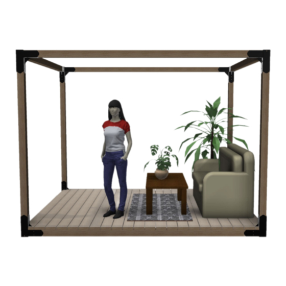
Figure 1: Items included in the kit, (
Items not included in this kit: wood, tools, some hardware.
1 |
P a g e
Installation Instructions
4x4 Floating Single Cubic Pergola Kit
Pergola Kits
������������������������ ���� �������� ���� ����
������������������������ ���� ����
4F-SC
).
•
Thoughtfully engineered
Brackets eliminate all wood-
joinery skills requirements.
•
Skills required: leveling
ground, drilling pilot
holes, and driving lag
screws into lumber.
•
Easy lift and place U-
channels eliminate need
for lifting equipment.
Super-easy assembly
work.
•
Self-aligning design
squares up structure
automatically.
Estimated Assembly
•
Time is less than 1-1/2
hours (not including
deck).
Advertisement
Table of Contents

Related Manuals for RioOutdoors 4F-SC


Summary of Contents for RioOutdoors 4F-SC
- Page 1 WARNING: If the information in these instructions is not followed exactly, weakening or failure of the erected structure may result causing property damage, personal injury, or loss of life. All brackets designed and sold by RioOutdoors.com are to be used for building pergolas only and are not to be used for other structure construction purposes.
-
Page 2: Table Of Contents
A properly sized pilot hole must be drilled before you attempt to drive lag screws into any pergola lumber member. See Table, below. Driving lag screws into lumber, without first drilling a pilot hole, can prevent the lag screw from driving fully into the wood or can lead to crack formation while driving the lag screw in, or later, as the wood dries naturally. -
Page 3: Safety And Warning Information
GENERAL INFORMATION 1.1 SAFETY AND WARNING INFORMATION 1.1.1 Building Permit & Inspection Requirements We recommend that you consult with your local building permit office and obtain advice and any required building permits and inspection approvals from the local building inspection department or the local authority over building codes. 1.1.2 Other Cautions CAUTION: Adhere to all safety requirements. -
Page 4: Tools Required
1.2 TOOLS REQUIRED Listed below, are common tools required for pergola projects. These tools are not included in this kit. Your pergola project may not require all tools. Select and acquire the tools for your project from the “Required for” column in this table. Description Tool Purpose Required for... -
Page 5: Contents Of Kit # 4F-Sc
If you wish to build a wooden deck as the floor for your floating pergola, you may wish to use our deck beam support brackets, SKU #24BS. This bracket can support 2x4 or 2x6 beams. You can order the required number of brackets at RioOutdoors.com. -
Page 6: List Of Materials That You Will Supply Recommended
1.5 LIST OF MATERIALS THAT YOU WILL SUPPLY, OR ARE RECOMMENDED This is the list of required materials which are not included in this kit. You will acquire these items locally for your project. Use this table to help you calculate your total project budget. Total Item Item... -
Page 7: Floating System
To do so, you must add 2x4 beams every 24” to support the deck boards. You may toenail the 2x4 beams in place or choose an easier and more precise mounting method using our 2x4 Beam Support Brackets (SKU# 24BS, available at RioOutdoors.com). P a g e... - Page 8 1.6.2 Floor Leveling and Preparation. Plan to assemble a floating pergola where you can excavate and create a level platform, at least, the overall outer dimensions of the pergola. If soil type is sandy, soft, or wet, you must consider adding concrete blocks or pier blocks under corners of pergola to prevent sinking into soil.
-
Page 9: Overall Pergola Size
1.7 OVERALL PERGOLA SIZE We have designed the corner elbow brackets to provide automatic squaring and alignment of the floating 4x4s. By following the instructions properly and securing the 4x4s to the elbow brackets as instructed, you will achieve a perfectly squared floating deck base for your pergola. -
Page 10: Ide Elevation Diagram
1.8 SIDE ELEVATION DIAGRAM Based on the height of the post used, the diagram below provides the side elevation profile for this pergola system. POST HEIGHT DIM A DIM B 92.5 104.5 116.5 128.5 140.5 Dim A, above, is the height of the post used. Dim B is the inner ceiling height of the pergola. Dim B is measured to the bottom surface of the header member. - Page 11 1.9 ASSEMBLING FLOOR CORNER 2-WAY ELBOW BRACKETS 1. Starting in one corner, slide one 2-way elbow over two adjacent 4x4s so the U-channels in the 2-way elbow bracket are over the 4x4s. 2. Place two shims under each 4x4 near the 2-way elbow. 3.
- Page 12 5. Wrap a piece of electrical tape around the drill bit, spaced 1-1/4” from the drill bit tip. This will act as a hole depth indicator when you drill each pilot hole. Pilot holes should be drilled at least 1-1/4” deep. A little bit deeper is acceptable but do not drill less than the required 1-1/4”...
- Page 13 7. Drive one ¼” X 1-1/4” lag screw through the pilot holes you drilled. 8. Repeate steps 8 and 9 for the other side of both U-channels. 9. Repeat Steps 5 to 9 for the other three corners. 10. Remove all shims from under the 4x4s. 11.
-
Page 14: Posts Installation
1.10 POSTS INSTALLATION 1. Slide a 4x4 post inside the open vertical tube in all four corners’ 2-way elbow bracket. 2. Identify the 5/16” holes in the inner faces of the 2-way elbow’s vertical tube. Drill 3/32” X 1-1/4” pilot holes in the center of all four 5/16”... -
Page 15: Post-Top Brackets Installation
1.11 POST-TOP BRACKETS INSTALLATION 1. Slide a 2-way elbow bracket’s tube over the 4x4 post top after aligning the header receiver u-channels in the proper directions. Let gravity work and pull the bracket all the way down on top of the post. 2. - Page 16 3. Wrap a piece of electrical tape around the drill bit, spaced 1-1/4” from the drill bit tip. This will act as a hole depth indicator when you drill each pilot hole. Pilot holes should be drilled at least 1-1/4” deep. A little bit deeper is acceptable but do not drill less than the required 1-1/4”...
- Page 17 5. Drive one ¼ x 1-1/4” Hex Lag Screw through each 5/16” hole into the pilot holes you drilled in step 4, using a 7/16” Socket and Rachet driver. Tighten down each screw. 6. Repeat steps 1 through 5 for each post top bracket. 17 | P a g e...
-
Page 18: Headers Installation
1.12 4X4 HEADERS INSTALLATION 1. Lift and place one 4x4 header into the U-channels of adjacent post-top bracket. Figure 2: Place one header 4x4 in U-channels. 2. Locate the two 5/16” holes on each vertical face of the U-channels holding the 4x4 header. Drill 3/32” X 1-1/4” deep pilot holes at the center of four 5/16”... - Page 19 3. Drive one ¼ x 1-1/4” Hex Lag Screw through each 5/16” hole into the pilot holes you drilled in step 8, using a 7/16” Socket and Rachet driver. Tighten down each screw. 4. Repeat steps 7-9 for the remaining 3 headers. 19 | P a g e...
-
Page 20: Nstalling Deck Board Support Beams
1.13 INSTALLING DECK BOARD SUPPORT BEAMS 1. Decide on which direction you would like the deck boards to run. Deck support beams run in a perpendicular direction to the deck boards. Support beams should be spaced, approximately, every 24” to support the deck boards. Using a pencil or marker, mark the center locations of each beam on the inside face of the floating 4x4s to which you will attach the beams. -
Page 21: Nstalling Deck Boards
5. Secure the 2x4s to brackets using #6 x 1” SS wood screws. Two screws on each side of the 2x4 Beam Support Bracket are required. 1.14 INSTALLING DECK BOARDS 1. Plan and lay down your deck boards starting in the center of the pergola. Work outward from the center in both directions. Use the thick end of a wood shim as a spacer to leave an 1/8”-1/4”... - Page 22 2. When you approach the vertical post corners, create notches in the deck boards ends to fit around the corner post bracket and the gussets. The gussets are 1/8” thick. Make a cut the width of a carbide tipped circular saw blade to create a clearance slot for the corner gussets.
- Page 23 RioOutdoors.com and provide us with your review. You may add accessories such as a swing or hammock, 2x4 beams or 2x6 rafters on top for shielding direct sunlight, or a sunshield fabric on top. Order accessories at RioOutdoors.com. Thank you for being a RioOutdoors.com customer.
-
Page 24: Conditions
Warranty protects against defect in manufacture only, unless herein specified otherwise. Any part(s) found to be defective during the warranty period as outlined above will be repaired or replaced at RioOutdoors.com’s option provided that the defective part is returned, if requested by RioOutdoors.com. Alternatively, RioOutdoors.com may at its own discretion fully discharge all its obligations under the warranty by refunding the verified purchase price of the product to the original purchaser. -
Page 25: Imitations Of Liability
Parts where the RioOutdoors.com logo has been altered, deleted, removed, or made illegible will void this warranty. Minor movement, expansion and contraction of the steel parts is normal and is not covered under the terms of this warranty.
Need help?
Do you have a question about the 4F-SC and is the answer not in the manual?
Questions and answers