Advertisement
Quick Links
Advertisement

Related Manuals for JTA Innovations MXS


Summary of Contents for JTA Innovations MXS
- Page 1 JTA Innovations 33” MXS www.modellmarkt24.ch www.modellmarkt24.ch...
- Page 2 Please Read For Your Safety The p oduct that you ha e ecei ed is not a toy. Please unde stand that model ai c aft ha e se e al mo ing pa ts and e uipment that if misused, can not only cause ha m to othe mate ials and objects, but also to you and othe s a ound ...
-
Page 3: Tools/Supplies Needed
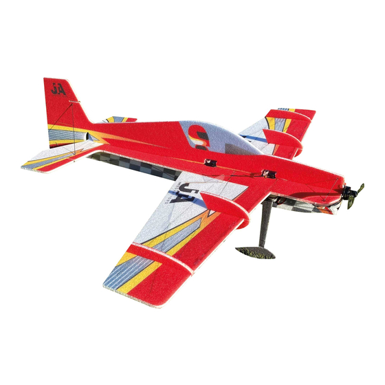
Tools/Supplies needed Including but not limited to: - Ruler -Building Adhesive -Hobbyknife with blades -Scissors -Heat gun or lighter for heat shrink -Assorted phillips and flat blade screwdrivers -Assortment of small drill bits -Drill -Needle nose pliers -Driver set -90 degree square -CA accelerator -Sandpaper... - Page 4 Continually providing high performance and durable EPP foamies, JTA Innovations took yet another leap forward with the release of the 33” MXS. In 6mm EPP just as the previous Gamebird, the MXS is an excellent compliment. Tested by high profile 3D/freestyle pilots here in the United States, the MXS has proven to satisfy some very technical demands.
- Page 5 Carbon fiber layout Aileron linkages: 70mm long each Elevator and rudder linkages: 400mm long each www.modellmarkt24.ch www.modellmarkt24.ch...
- Page 6 www.modellmarkt24.ch www.modellmarkt24.ch...
- Page 7 As shown above, the aileron bracing is done using flat carbon fiber glued into the slots creating durability for the aileron. Please see the carbon fiber diagram for your airframe to determine which size carbon strips are to be used. www.modellmarkt24.ch www.modellmarkt24.ch...
- Page 8 Wing bracing shown above. The center wing spar is the supplied carbon fiber square stock. Cowl glued to the fuselage. www.modellmarkt24.ch www.modellmarkt24.ch...
- Page 9 The horizontal piece of the fuselage also uses flat carbon fiber spanning the entire length from the rear wing spar to the horizontal stab spar. Elevator flat spar and h-stab flat spar shown above. www.modellmarkt24.ch www.modellmarkt24.ch...
- Page 10 Now that rigidity is established, it is very important to break in the hinges by flexing them all the way over and weighing them down. Let them rest for at least 60 minutes. www.modellmarkt24.ch www.modellmarkt24.ch...
- Page 11 You can now prepare the bottom half of the fuselage. Test fit this into each slot as shown above before glueing. www.modellmarkt24.ch www.modellmarkt24.ch...
- Page 12 If deciding to place glue on the horizontal part of the fuselage, you can mark out where the glue will be placed as shown above after test fitting the fuselage. www.modellmarkt24.ch www.modellmarkt24.ch...
- Page 13 Using the marks that you just made, place your glue along the fuselage. www.modellmarkt24.ch www.modellmarkt24.ch...
- Page 14 It is extremely important to make sure that the bottom vertical part of the fuselage stays 90 degrees to the horizontal fuselage while the glue is setting. This can have a huge effect on the flying characteristics. www.modellmarkt24.ch www.modellmarkt24.ch...
- Page 15 Now that the bottom fuselage piece is glued into place, you can locate the carbon fiber rods used for the wing bracing. Shown above is the wing joiner used to guide the wing bracing. Some airframes may have a larger gusset or joiner that overlaps the leading edge.
- Page 16 Shown above is the wing bracing glued into the bottom part of the fuselage. www.modellmarkt24.ch www.modellmarkt24.ch...
- Page 17 Just like the aileron bracing, it is very important to use weight towards the wing tip while the carbon wing bracing is setting to keep the leading edge of the wing as straight as possible. www.modellmarkt24.ch www.modellmarkt24.ch...
- Page 18 Shown above is one of the carbon fiber landing gear legs that come pre-glued to the axle. The larger of the two EPP foam circular collars will slide on first. No need to apply glue to anything quite yet. www.modellmarkt24.ch www.modellmarkt24.ch...
- Page 19 Next, with no glue needed, slide one of the wheels on to the axle all the way up to the first foam collar. Make sure it is spinning freely. www.modellmarkt24.ch www.modellmarkt24.ch...
- Page 20 Now locate the plywood/carbon fiber laminated collar to slide up next to the plastic wheel. Once again, do not apply glue yet as the tire will need to spin as freely as possible around the axle. www.modellmarkt24.ch www.modellmarkt24.ch...
- Page 21 Locate the smaller of the two circular foam collars to slide onto the axle next. www.modellmarkt24.ch www.modellmarkt24.ch...
- Page 22 Lastly, locate one of the wheel pants. You can place a bit of adhesive on the last foam collar before sliding the wheel pant on to the axle. If desired, you can place some adhesive on the outside of the wheel pant where the carbon fiber axle ends.
- Page 23 Shown above is both landing gear legs in place. You will find the slots cut in the side of the bottom of the fuselage to slide each landing gear leg into. Make sure that the bottom of each leg is placed to where the airplane will sit level on the ground.
- Page 24 Locate the EPP landing gear cover that will be placed over the carbon fiber landing gear leg. Test fit this piece, then glue it on over the carbon fiber using the pre-cut slot. www.modellmarkt24.ch www.modellmarkt24.ch...
- Page 25 Shown above is the bottom fuse bracing for the rear of the fuselage. Lengths found in diagram. www.modellmarkt24.ch www.modellmarkt24.ch...
- Page 26 Shown above is the rest of the bottom fuselage bracing up to the wing bracing. You should be able to notice the dots marked to help guide where each rod will be placed. Lengths found in diagram. www.modellmarkt24.ch www.modellmarkt24.ch...
- Page 27 Above is other side of the fuselage carbon fiber arrangement. www.modellmarkt24.ch www.modellmarkt24.ch...
- Page 28 Locate the short flat carbon fiber piece that will be used as the tail piece for taxiing, taking off, and landing. www.modellmarkt24.ch www.modellmarkt24.ch...
- Page 29 Glue the tailpiece into place as shown above while making sure that it is on the same angle of the bottom of the fuselage to ensure that the airframe will sit level. www.modellmarkt24.ch www.modellmarkt24.ch...
- Page 30 You can now prepare your servo arms. Above is the provided double arm to be added on to the aileron servo arm that comes with the servo. Using the extension will provide the maximum amount of aileron throw. To join the two arms, use carbon fiber rods as shown above and glue them in through the holes lined up on each arm.
- Page 31 Before placing the servo arm on the servo, locate the mini EZ connector. These connectors will be used to secure the linkage to the servo arm. Slide the top metal piece into the end of the servo arm and then fasten the bottom plastic piece through the pin.
- Page 32 After you electronically center your aileron servo by plugging it into your receiver and powering it on with zero sub trim and trim, you can glue it into the servo slot that is the most forward on the airframe with the output shaft facing rear.
- Page 33 For both the elevator and rudder servos, face the output shaft towards the rear. For the MXS, position the servo arm towards the bottom of the airplane and run the linkage along the bottom part of the fuselage.
- Page 34 Shown above is the rudder servo mounted. www.modellmarkt24.ch www.modellmarkt24.ch...
- Page 35 Locate the control horns in the provided kit. You will find three longer horns and one shorter one. Two long ones will be used for the ailerons and one long horn for the rudder. The shorter one will be used on the elevator. You will notice a cutout on the bottom of the elevator horn that will fit over the elevator spar.
- Page 36 Locate the carbon fiber rods to be used for the aileron linkages (lengths shown in diagram). This will be cut and used for the two aileron linkages. Also locate the straight metal piece as shown above. Use regular CA to glue these two together.
- Page 37 Shown above is the entire aileron linkage assembly for one aileron. Notice the heat shrink over each glued end, as well as the straight end clamped into the mini EZ connector on the servo arm. www.modellmarkt24.ch www.modellmarkt24.ch...
- Page 38 Shown above is the elevator linkage. Notice how the 4 guides are slid over the linkage and the heatshrink is cut and slid on before the Z bend is glued. The rudder linkage will be done the same way later on. You will be able to tell where the guides will need to be glued in based on the slots in the fuselage.
- Page 39 Above is the finished elevator linkage setup with the guides glued into the fuselage and the elevator centered and clamped into the mini EZ connector. www.modellmarkt24.ch www.modellmarkt24.ch...
- Page 40 Once the aileron and elevator linkages are set up, use the same process as glueing the bottom of the fuse to glue the top of the fuselage into place. Once again, it is important to keep this as straight as possible. Now that the top of the fuselage is glued in, you can glue the other rear carbon fiber rods to help strengthen the tail as shown above.
- Page 41 from the bottom of the horizontal tail to the rear of the bottom vertical fuselage. Make sure they are glued in a location that allows for full down elevator throw. Shown above is the carbon rod that will go on each side of the fuselage. It will be used to strengthen the horizontal stab and vertical stab.
- Page 42 The final piece used for carbon fiber bracing will be the rod used at the front of the airframe. Make sure that the fuselage is straight while these pieces are setting. You can now locate the final long control horn and glue it into the slot on the side of the rudder.
- Page 43 Locate the motor mount as shown above. Test fit the motor mount to the front of the fuselage by bending the attached tabs 90 degrees and sliding it on without glue. Once test fitted, place adhesive on the inside of the motor mount covering every spot, then place again on the front of the fuselage making sure everything is flush and lined up correctly.
- Page 44 Notice above the plate glued onto the side of the fuselage. This can be used to mount the electronic speed controller on the other side of the fuselage. The two cutouts on the top and bottom of the plate is where the provided velcro strap will slide through.
- Page 45 The center of gravity and battery placement will depend on equipment used and personal flying preferences. The long piece of velcro mounted above is the location of the battery for this setup. To save space on the other side of the fuselage, the battery connector is put through to the opposite side of the ESC and receiver.
- Page 46 Shown above is the motor mounted to the provided motor mount. If desired, locate the side force generators that will be glued into the counterbalances of the ailerons. *Some airframes may require the SFGs to be glued into different locations along the wing.* www.modellmarkt24.ch www.modellmarkt24.ch...
- Page 47 Shown above are the pieces included for the stand assembly. Here is the stand fully assembled. www.modellmarkt24.ch www.modellmarkt24.ch...
- Page 48 We are anxiously awaiting your feedback on this product and I hope I will get the pleasure of meeting you in person if I have not yet already. Once again, thank you! God bless, Jase Dussia - Owner/Founder JTA Innovations, LLC www.modellmarkt24.ch www.modellmarkt24.ch...
Need help?
Do you have a question about the MXS and is the answer not in the manual?
Questions and answers