Advertisement
Quick Links
Advertisement

Related Manuals for JTA Innovations Gamebird


Summary of Contents for JTA Innovations Gamebird
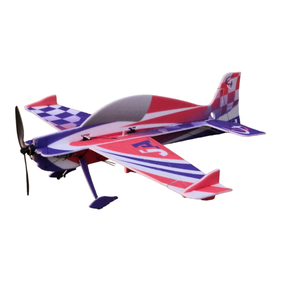
- Page 1 JTA Innovations 33” Gamebird ...
- Page 2 JTA Innovations is not accountable or responsible for any events or incidents that cause damage, injury, or even death. After purchase and ...
-
Page 3: Tools/Supplies Needed
Tools/Supplies needed Including but not limited to: - Ruler -Building Adhesive -Foam safe CA and/or regular CA -Hobbyknife with blades -Scissors -Heat gun or lighter for heat shrink -Assorted phillips and flat blade screwdrivers -Assortment of small drill bits -Drill -Needle nose pliers -Driver set... - Page 4 Excelling in all areas of flying, the Gamebird is aimed to please any type of RC aerobatic pilot, whether that is the beginner 3D pilot or advanced freestyle pilot. Not many other foamies have the wide range of flight envelope of the JTA Gamebird.
- Page 5 * Below are photos of the new construction version for reference. This replaces some features (aileron gusset bracing for example) that are listed later on in the manual. If you are assembling an older version, please move on to the manual where the control surface break in begins.* ...
- Page 8 ...
- Page 9 In order to get a consistent full range of all control surfaces during flight and setup, we recommend that the first thing you do after unboxing is weighing down the control surfaces as shown above. Each surface will take about 60-120 minutes to complete, then you will notice that it will be easier to move the surface to full deflection.
- Page 10 Pictured above is the bottom of the fuselage on some wax paper, as well as the wing panels and the horizontal tail. Test fit these pieces, then when confirmed, glue into place.
- Page 11 Once the horizontal tail is glued into place, locate the elevator spar. You will see the location where this will go in the elevator. This will be the shorter of the two carbon fiber square rods (the other will be used for the wing spar).
- Page 12 Pictured above is the wing spar in place. Test fit to make sure it crosses through the fuselage with no issues before glueing.
- Page 13 Locate the joiner that has one hole cut in the top. This will be the aileron brace joiner. You will find two (one for each aileron). Glue this into place while making sure it is 90 degrees to the aileron surface.
- Page 14 The other joiner that has two holes in the top will be for the wing bracing. Also, the cutout at the bottom will fit over the top of the wing spar. Glue this piece into each wing also making sure that it is 90 degrees to the wing.
- Page 15 Pictured above and below are all four joiners in place, as well as the wings and horizontal tail.
- Page 17 Shown above is the aileron bracing meeting together at the joiner. You should be able to notice the dots on the inboard and outboard sides of the ailerons to help you determine where to glue the carbon rods. It is best to have weight on both sides of each aileron to prevent warping while the glue is setting.
- Page 18 You can now prepare the bottom half of the fuselage. Test fit this into each slot as shown above before glueing.
- Page 19 If deciding to place glue on the horizontal part of the fuselage, you can mark out where the glue will be placed as shown above after test fitting the fuselage.
- Page 20 Using the marks that you just made, place your glue along the fuselage.
- Page 22 It is extremely important to make sure that the bottom vertical part of the fuselage stays 90 degrees to the horizontal fuselage while the glue is setting. This can have a huge effect on the flying characteristics.
- Page 23 Now that the bottom fuselage piece is glued into place, you can locate the carbon fiber rods used for the wing bracing. Shown above is the wing joiner used to guide the wing bracing. You will also find dots towards the tip of each wing to determine where to glue the carbon rods.
- Page 24 Shown above is the wing bracing glued into the bottom part of the fuselage.
- Page 25 Just like the aileron bracing, it is very important to use weight towards the wing tip while the carbon wing bracing is setting to keep the leading edge of the wing as straight as possible.
- Page 26 Shown above is weight on both the counterbalance of the aileron and the tip of the wing to keep the entire leading and trailing edge straight. It is also a good idea to put weight towards the root of the aileron and wing.
- Page 27 Shown above is one of the carbon fiber landing gear legs that come pre-glued to the axle. The larger of the two EPP foam circular collars will slide on first. No need to apply glue to anything quite yet.
- Page 28 Next, with no glue needed, slide one of the wheels on to the axle all the way up to the first foam collar. Make sure it is spinning freely.
- Page 29 Now locate the plywood/carbon fiber laminated collar to slide up next to the plastic wheel. Once again, do not apply glue yet as the tire will need to spin as freely as possible around the axle.
- Page 30 Locate the smaller of the two circular foam collars to slide onto the axle next.
- Page 31 Lastly, locate one of the wheel pants. You can place a bit of adhesive on the last foam collar before sliding the wheel pant on to the axle. If desired, you can place some adhesive on the outside of the wheel pant where the carbon fiber axle ends.
- Page 32 Shown above is both landing gear legs in place. You will find the slots cut in the side of the bottom of the fuselage to slide each landing gear leg into. Make sure that the bottom of each leg is placed to where the airplane will sit level on the ground.
- Page 33 just behind it (as pictured above) is 107mm.
- Page 34 Locate the EPP landing gear cover that will be placed over the carbon fiber landing gear leg. Test fit this piece, then glue it on over the carbon fiber using the pre-cut slot.
- Page 35 Shown above is the bottom fuse bracing for the rear of the fuselage. The lengths of the carbon rods shown above (from aft to forward): 130mm, 140mm, 119mm...
- Page 36 Shown above is the rest of the bottom fuselage bracing up to the wing bracing. You should be able to notice the dots marked to help guide where each rod will be placed. The carbon rod lengths from aft to forward (as shown above): 140mm, 119mm, 119mm, 130mm...
- Page 37 Shown above is the 130mm carbon rod that will be placed just aft of the wing bracing location.
- Page 38 Above is other side of the fuselage carbon fiber arrangement.
- Page 39 Locate the short flat carbon fiber piece that will be used as the tail piece for taxiing, taking off, and landing.
- Page 40 Glue the tailpiece into place as shown above while making sure that it is on the same angle of the bottom of the fuselage to ensure that the airframe will sit level.
- Page 41 You can now prepare your servo arms. Above is the provided double arm to be added on to the aileron servo arm that comes with the servo. Using the extension will provide the maximum amount of aileron throw. To join the two arms, use carbon fiber rods as shown above and glue them in through the holes lined up on each arm.
- Page 42 Before placing the servo arm on the servo, locate the mini EZ connector. These connectors will be used to secure the linkage to the servo arm. Slide the top metal piece into the end of the servo arm and then fasten the bottom plastic piece through the pin.
- Page 43 After you electronically center your aileron servo by plugging it into your receiver and powering it on with zero sub trim and trim, you can glue it into the servo slot that is the most forward on the airframe with the output shaft facing rear.
- Page 44 Shown above is the glued in elevator servo. For the elevator, use the middle servo slot that is on the side of the fuselage. The arms used for the elevator and rudder servos are the singles. For both the elevator and rudder servos, face the output shaft towards the rear.
- Page 45 Shown above is the rudder servo mounted in the furthest rear servo slot.
- Page 46 Locate the control horns in the provided kit. You will find three longer horns and one shorter one. Two long ones will be used for the ailerons and one long horn for the rudder. The shorter one will be used on the elevator. You will notice a cutout on the bottom of the elevator horn that will fit over the elevator spar.
- Page 47 Locate the long 356mm carbon fiber rod. This will be cut and used for the two aileron linkages. Also locate the straight metal piece as shown above. Use regular CA to glue these two together. The straight metal piece will be what slides into the mini EZ connector on the servo arm of the aileron.
- Page 48 Shown above is the entire aileron linkage assembly for one aileron. Notice the heat shrink over each glued end, as well as the straight end clamped into the mini EZ connector on the servo arm.
- Page 49 Shown above is the elevator linkage (all 365mm long). Notice how the 4 guides are slid over the linkage and the heatshrink is cut and slid on before the Z bend is glued. The rudder linkage will be done the same way later on. You will be able to tell where the guides will need to be glued in based on the slots in the fuselage.
- Page 50 Above is the finished elevator linkage setup with the guides glued into the fuselage and the elevator centered and clamped into the mini EZ connector. Once the aileron and elevator linkages are set up, use the same process as glueing the bottom of the fuse to glue the top of the fuselage into place. Once again, it is important to keep this as straight as possible.
- Page 51 Now that the top of the fuselage is glued in, you can glue the other rear carbon fiber rods to help strengthen the tail as shown above. They will be mounted from the bottom of the horizontal tail to the rear of the bottom vertical fuselage.
- Page 52 Shown above is the carbon rod that will go on each side of the fuselage. It will be used to strengthen the horizontal stab and vertical stab. The length is 170mm. The final piece used for carbon fiber bracing will be the 65mm long rod used at the front of the airframe.
- Page 53 You can now locate the final long control horn and glue it into the slot on the side of the rudder. This will be used for the rudder linkage that will be constructed in the same way as the one used for the elevator. Once again, the length for that linkage is 365mm.
- Page 54 Locate the motor mount as shown above. Test fit the motor mount to the front of the fuselage by bending the attached tabs 90 degrees and sliding it on without glue. Once test fitted, place adhesive on the inside of the motor mount covering every spot, then place again on the front of the fuselage making sure everything is flush and lined up correctly.
- Page 55 Shown above is the ESC mounted using the velcro strap and a supplied zip tie is used to tie the ESC wires together.
- Page 56 The center of gravity and battery placement will depend on equipment used and personal flying preferences. The long piece of velcro mounted above is the location of the battery for this setup. To save space on the other side of the fuselage, the battery connector is put through to the opposite side of the ESC and receiver.
- Page 57 If desired, locate the side force generators that will be glued into the counterbalances of the ailerons.
- Page 58 Shown above are both sides of the SFGs glued into place on one of the counterbalances. Shown above are the pieces included for the stand assembly. Here is the stand fully assembled.
- Page 59 We are anxiously awaiting your feedback of this product and I hope I will get the pleasure of meeting you in person if I have not yet already. Once again, thank you! God bless, Jase Dussia - Owner/Founder JTA Innovations, LLC...
Need help?
Do you have a question about the Gamebird and is the answer not in the manual?
Questions and answers