Advertisement
Quick Links
Advertisement

Related Manuals for JTA Innovations Yak 54


Summary of Contents for JTA Innovations Yak 54
- Page 1 JTA Innovations ” Yak www.modellmarkt24.ch www.modellmarkt24.ch...
- Page 2 Please Read For Your Safety The p oduct that ou ha e ecei ed is not a to . Please unde stand that model ai c aft ha e se e al mo ing pa ts and e uipment that if misused, can not onl cause ha m to othe mate ials and objects, but also to ou and othe s a ound ...
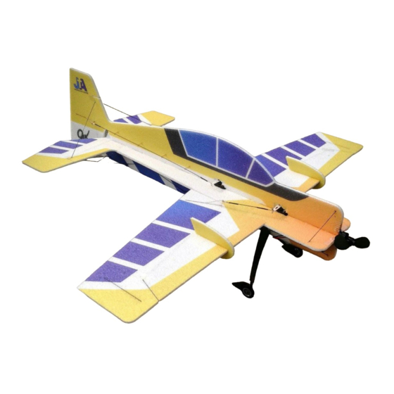
- Page 3 We are pleased to introduce the first development of the JTA Innovations line of foamies, the 32” Yak 54. The Yak has always been a popular and classic platform within the RC aerobatic community. Designed with all styles of foamy...
-
Page 4: Tools/Supplies Needed
Tools/Supplies needed Including but not limited to: - Ruler -Foam safe CA or preferred glue for construction and regular CA for linkages -Hobby knife with blades -Scissors -Heat gun or lighter for heat shrink -Assorted phillips and flat blade screwdrivers -Assortment of small drill bits -Drill -Needle nose pliers... - Page 5 * Belo a e photos of the ne const uction e sion fo efe ence. This eplaces some featu es aile on gusset b acing fo e ample that a e listed late on in the manual. If ou a e assembling an olde e sion, please mo e on to the ...
- Page 6 www.modellmarkt24.ch www.modellmarkt24.ch...
- Page 7 www.modellmarkt24.ch www.modellmarkt24.ch...
- Page 8 In order to get consistent full range of all control surfaces during flight and setup, we recommend that the first thing you do after unboxing is weighing down the control surfaces as shown above. Each surface will take about www.modellmarkt24.ch www.modellmarkt24.ch...
- Page 9 60-120 minutes to complete, then you will notice that it will be easier to move the surface to full deflection. Now, locate the horizontal piece of the fuselage as well as both wings. Make sure the fuselage is flat inverted and test fit each wing panel.
- Page 10 Now that the wing is glued, locate the wing spar. This is the square carbon fiber that will be the length of the wing itself. Test fit into the slot in the wing and make sure it is flush even at the spots where the wing joins with the fuse. Once this is done, you can then glue the spar in.
- Page 11 notice there is a cutout for this piece. Test fit, glue, then repeat for the other aileron. Locate the triangular joiner that will be placed on the underside of each aileron. Once you make sure that it fits clean and snug into the cutout, you can glue this piece in and repeat to the other side.
- Page 12 be pre-cut. You may also be able to spot the black dots where carbon can be referenced for placing. Be sure to provide a good connection for the carbon by poking through the foam. Test fit the horizontal stab/elevator into the rear of the fuselage.
- Page 13 Making sure that everything is 90 degrees and flat, it is important to test fit the underneath side of the vertical fuselage. The fit should be fairly snug, so do not glue any spots until you know that each tab will be inserted fully along the fuse.
- Page 14 As shown in the photo above, a flat piece of carbon fiber will be used for the tailwheel purpose and allow the aircraft to rest and taxi on the ground without coming in contact with the foam. This will be glued to the bottom vertical piece of the fuselage.
- Page 15 Shown above is the entire assembly for the landing gear. The square carbon fiber landing gear is already glued into the axles. You will find the wheels as well as three total collars (2 foam pieces, and 1 wood/carbon laminated piece). www.modellmarkt24.ch www.modellmarkt24.ch...
- Page 16 Along with the EPP wheel spat, there is an additional piece of EPP that is the same shape that will be glued together to provide strength for the rear part of the spat. The photo above shows the two pieces glued together. www.modellmarkt24.ch www.modellmarkt24.ch...
- Page 17 The wheel spat will be the first thing that is put on the axle. This will go all the way flush to the landing gear/axle joiner. Add a drop of glue to put this into place once it is positioned to your desire.
- Page 18 Now, the tire/wheel is ready to be placed on the axle. Do not add any glue so that it can rotate freely around the axle. Next, slide on the smaller piece of foam that will act as the collar on the outside of the wheel. Once again, do not add any glue to this piece.
- Page 19 Lastly, apply the small wooden collar that will hold the wheel onto the axle. You can add a small drop of glue to ensure that this piece will not slide off. Pictured above is the landing gear mounted on the airplane. You will notice that each landing gear side is crossed through to the opposite side of the airplane.
- Page 20 that the landing gear positioning is correct to allow the airplane to sit level on the ground. Once this is confirmed, you can then glue in the carbon fiber into the opposite sides of the wing as well as where the two pieces of the landing gear join in the fuse.
- Page 21 Locate the 2 side force generators. You will notice that one side of each SFG has cut outs. Make sure that these cutouts are facing the bottom as this is where the carbon fiber bracing will be passing through on the bottom of the wing. Make sure that the SFG fits snug and flush with the wing.
- Page 22 Make sure that the carbon bracing is slid all the way down into the slots on the bottom of the SFG. These braces are 300mm long. Repeat this process for the other wing. This 190mm flat carbon fiber piece will be used to strengthen the bottom of the fuselage from the front of the fuse through the landing gear location.
- Page 23 easier to apply the servo arms when the servo is not installed in the airframe. The aileron servo will be the most forward and the rudder servo will be the farthest aft. These two servos are shown above. This is the location for the elevator servo. It will be placed between the aileron and rudder servo and on the underside of the fuselage.
- Page 24 The control horns will be placed and glued into the slots of the appropriate control surfaces. Make sure when applying the control horns that they are flush and that the hole for the linkage is directly above the hinge line. It may be a good idea to scuff the sides of them with sandpaper.
- Page 25 Shown above is the carbon fiber arrangement that will be used to brace the fuselage. Most will be used for the underside, but some will be used for the top in a later step. Shown is the configuration for the underside bracing of the “cowling”...
- Page 26 You can now brace along the underside of the fuselage. The 4 pieces that are the same length are 125mm. The long piece that extends from the fuselage to the horizontal stab is 155mm. In order to extend the length of the servo arm to provide maximum travel to the control surfaces, you may be interested in using the supplied servo arms.
- Page 27 accomplish this. Shown above, carbon fiber rod is placed through both arms to provide strength to the connection. Once fixed in place, you can cut the carbon fiber to a shorter length. You may also be interested in placing carbon fiber in two holes per side of the servo arm.
- Page 28 piece through the hole in the arm, then fully clamp the bottom piece around the pin. The flat side of the bottom piece will be pushed against the servo arm. Leave the top screw loose for now until the control linkage is slid through. Above are what will be used for each end of the control linkages.
- Page 29 This is the full linkage assembly and configuration for the aileron servo setup. You will notice that each end of the linkage is secured to carbon fiber inside heat shrink. Before heat shrinking, scuff the carbon with sandpaper, then use REGULAR ...
- Page 30 For the elevator linkage, test fit the small guides into the cutouts as shown above. There are 8 total in the kit (4 for elevator, 4 for the rudder). Shown above is the elevator linkage connected to the Z bend using the same process that was used for the aileron (CA, then heat shrink over top).
- Page 31 connected to the EZ connector on the servo arm. This is because heat shrinking still needs to be done and if the guides were glued in while heat shrinking was attempted, it may be too close to the foam causing the foam to melt. Once the servo is centered, and both sides of the linkage are glued and tightened with heat shrink, you can now glue in place the guides for the linkage.
- Page 32 Now that the aileron and elevator servos are centered and linked up, you can install the upper half of the vertical fuselage. Just as the rest of the pieces prior, test fit first before glueing. Depending on the servos being used, you may need to cut the foam around the servos to allow a flush and snug fit all the way along the fuselage.
- Page 33 Notice the joining of the top of the fuse to the bottom of the fuse at the point of the tailpiece. Make the connection so that the bottom of the fuse is one straight line all the way to the trailing edge of the rudder.
- Page 34 Locate the final control horn needed for assembly. The rudder uses the same type of control horn as the aileron which is on of the longer of the 4. If necessary, scuff the sides with sandpaper, test fit making sure the hole is directly above the hinge line, then glue in place.
- Page 35 For bracing of the top of the horizontal stab to the vertical stab, 2 180mm carbon rods will be used in the configuration shown above. Now that the top part of the fuselage is glued in, you can finish the bracing for the bottom by including the 2 pieces that will connect the horizontal stab to the vertical stab aft of the tailpiece (behind the connection made when glueing the top of the fuse to the bottom).
- Page 36 The rudder servo linkage connection is now ready to be accomplished using the same technique as the elevator linkage. These guides will be mounted horizontally to the side of the fuselage. Just as the ones used for the elevator, you will see the cutouts pre made in the fuselage. Do not glue them in until the Z bend and straight link are both secured to the carbon linkage using REGULAR CA and heat shrink.
- Page 37 Line up the holes in the motor mount that is mounted on the motor itself to the mount that is mounted on the airplane. If needed, pre drill the holes needed to mount the screws. The plate shown above is used to assist with the mounting the electronic speed controller.
- Page 38 the plate is glued. These slots will be guiding the velcro strap that is provided with the kit to mount the ESC. Shown above is the ESC side, the opposite side is where the plate was mounted. Notice the velcro strap coming through the fuselage and around the ESC.
- Page 39 If you would like, the battery can be mounted on the opposite side of the receiver and ESC to save some space. To do this, simply cut a small hole into the foam and and guide the connector through to the battery side of the airplane. **Location of the battery is personal preference and is dependent on the size and weight of the battery, as well as where the RX is located.
- Page 40 The stand fully assembled. For any type of answer regarding assembly or other topics related to this product contact us at jtainnovations@gmail.com www.modellmarkt24.ch www.modellmarkt24.ch...
- Page 41 We are anxiously awaiting your feedback of this product and I hope I will get the pleasure of meeting you in person if I have not yet already. Once again, thank you! God bless, Jase Dussia - Owner/Founder JTA Innovations, LLC www.modellmarkt24.ch www.modellmarkt24.ch...
Need help?
Do you have a question about the Yak 54 and is the answer not in the manual?
Questions and answers