Advertisement
Quick Links
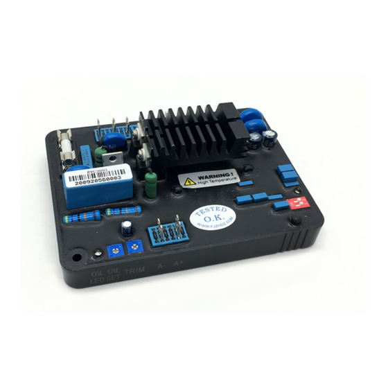
Generator Automatic Voltage Regulator
1. INTRODUCTION
The EVC300i Voltage Regulator is thyristor base to control the DC exciter field power of conventional
50 or 60 Hz brushless generators. The AVR circuitry includes under speed and over load protection
features. Excitation power is derived directly from the generator terminals.
2. ENVIRONMENTAL
2.1. Operating temperature:
2.2. Storage temperature:
2.3. ALTITUDE:
Less than 2800 meter
2.4. RELATIVE HUMIDITY:
3. TECHNOLOGY SPECIFICATION
Sensing Input
Terminal V - V
for 220 Vac
220
Terminal V - V
for 400 Vac
380
Power Input
Voltage: 180 to 250 Vac
Frequency: 50 Hz or 60 Hz
Voltage Adjust Range
180 - 300 Vac, 300 - 520 Vac
Field Resistance
Recommend 9 - 24
Voltage Regulation
< 1%
±
Output Voltage
Maximum 90 Vdc @ 240 Vac
Output Current
Maximum continuous: 6.3 A @ 240 Vac
10 second forcing: 10 A @ 240 Vac
OPERATING MANUAL FOR AUTOMATIC VOLTAGE REGULATOR
MODEL NO : EVC300i
EVC300i
Operation Manual
-30 to 80°C (-22 to 176 F)
-40 to 80°C (-40 to 176 F)
<90%
Paralleling
Internal burden and adjustment for 0 to 10%
droop at 1 A, 0.8 PF, (from external CT)
Voltage Buildup
4Vac, 30 Hz
External Volts Adjustment
At least
±
10% with 100k ohm 1 watt trimmer
Thermal Drift
0.05% per 'C' change in AVR ambient
Analog Voltage Input
±5VDC, adjustable output voltage is no less than
2% for 1VDC (i.e. for ±5VDC it come out to be
±10%)
Current Compensation
In : 1A Input
Not Less than 10 % @ P.F. = 0.8
Dimensions
122 mm L x 93 mm W x 38 mm H
Weight
300
±
10g
Page 1 of 7
Updated on 02 Feb2015
Advertisement

Related Manuals for ENGGA EVC300i


Summary of Contents for ENGGA EVC300i
- Page 1 Operation Manual 1. INTRODUCTION The EVC300i Voltage Regulator is thyristor base to control the DC exciter field power of conventional 50 or 60 Hz brushless generators. The AVR circuitry includes under speed and over load protection features. Excitation power is derived directly from the generator terminals.
-
Page 2: Mechanical Specification
OPERATING MANUAL FOR AUTOMATIC VOLTAGE REGULATOR MODEL NO : EVC300i 4. MECHANICAL SPECIFICATION 4.4 mm 122 mm DRAWING TRIM S 1 ON - Increase in Response Time. OFF - Response as per STAB pot Set SW : ON - 60 HZ... -
Page 3: Dip Switch
OPERATING MANUAL FOR AUTOMATIC VOLTAGE REGULATOR MODEL NO : EVC300i AVR can be mounted directly on the generator, switchgear or control panel that conforms to the mounting specification. All voltage readings are to be taken with an average-reading voltmeter. Meggers and high-potential test equipment must not be used with AVR connected to generator. -
Page 4: Operational Test
57.2 Hz for 60 Hz applications. For 50 Hz applications, the frequency roll-off is factory preset to between 46.8 and 47.2 Hz. To operationally test any EVC300i, refer to Figure 5 To reset the frequency roll-off, proceed as follows: and perform the following steps: a. - Page 5 OPERATING MANUAL FOR AUTOMATIC VOLTAGE REGULATOR MODEL NO : EVC300i Exciter Armature Stator Wire Field IN : 100K/1W Note : All doted lines are optional connections. UFRO LED SW : ON - 60 HZ OFF -50 HZ SW1 ON - Increase in Response Time.
- Page 6 OPERATING MANUAL FOR AUTOMATIC VOLTAGE REGULATOR MODEL NO : EVC300i Exciter Armature Stator Wire Field IN : 100K/1W Note : All doted lines are optional connections. UFRO LED SW : ON - 60 HZ OFF -50 HZ SW1 ON - Increase in Response Time.
- Page 7 OPERATING MANUAL FOR AUTOMATIC VOLTAGE REGULATOR MODEL NO : EVC300i 230Vac/50Hz LAMP 220V100W UFRO LED SW : ON - 60 HZ OFF -50 HZ SW1 ON - Increase in Response Time. OFF - Response as per STAB pot Set Figure 5. Operational Test...
Need help?
Do you have a question about the EVC300i and is the answer not in the manual?
Questions and answers