Table of Contents
Advertisement
Quick Links
Advertisement
Table of Contents

Related Manuals for Metermatic EM6


Summary of Contents for Metermatic EM6
- Page 1 Installation Manual...
-
Page 2: Table Of Contents
3.1. Mechanical installation....................6 3.1.1. EM6 ........................6 3.2. Electrical installation ..................... 7 3.2.1. EM6 Installation Block diagram ................7 J1 – Input power ..................... 9 3.2.2. 3.2.2.1. APM-100 ......................9 3.2.2.2. DPM-100 ......................10 J2 – Relay outputs ....................11 3.2.3. - Page 3 Installation Manual 8.1.9. J12 & J13 Pulsar interface (see section 3.2.11.2) ..........36 8.1.10. J12 & J13 Pulsar interface (see section 3.2.11.3) ..........36 8.1.11. J14 Dallas iButton interface ................36 8.1.12. GSM–100 ......................37 Rev 3 Page 3 S. Robinson September 2017...
-
Page 4: Introduction
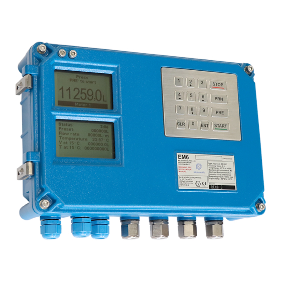
EM6 is mounted on bulk petroleum vehicles or gantries and is designed to electronically measure and control all loading/offloading processes. The EM6 is housed in a combined Exd and Intrinsic safe enclosure, which has approximate dimensions of 347mm x 226mm x 91mm. Four M10 bolts secures the EM6 onto the vehicle or gantry installation. -
Page 5: Pre Installation Precautions
The equipment is only certified for use in ambient temperatures in the range -20°C to +60°C and should not be used outside this range. d) If welding is to be done on a vehicle or structure after the EM6 has been installed, then all connections to the EM6 must be isolated. -
Page 6: Installation
12.9 SHCH (socket head cap screws). Washers are fitted to the fasteners up to a maximum of 3.1mm thick h) The EM6 System is group IIA equipment and may connect to group IIA equipment. It may be used with flammable gases and vapors with apparatus group IIA and with the temperature classes T1, T2, T3 and T4. -
Page 7: Electrical Installation
3.2. Electrical installation 3.2.1. EM6 Installation Block diagram... - Page 8 Installation Manual Failure to follow the instructions flagged with the icon shown on the left will invalidate the Intrinsically Safe (IS) approvals of the equipment. This could result in dangerous conditions. Rev 3 Page 8 S. Robinson September 2017...
-
Page 9: J1 - Input Power
Installation Manual 3.2.2. J1 – Input power 3.2.2.1. APM-100 Identified with “APM-100” marking on the silkscreen of the PCB 250V Input Only Minimum 0.5mm² wire required It is important not exceed the SAFETY PARAMETS of J1 (see section 7.1 below). Failure to do this will invalidate the IS certification. -
Page 10: Dpm-100
Installation Manual 3.2.2.2. DPM-100 Identified with “DPM-100” marking on the silkscreen of the PCB 24V Input Only Minimum 0.5mm² wire required It is important not exceed the SAFETY PARAMETS of J1 (see section 7.1X below). Failure to do this will invalidate the IS certification. Rev 3 Page 10 S. -
Page 11: J2 - Relay Outputs
Installation Manual 3.2.3. J2 – Relay outputs The relays are internally limited with a 5A fuse – F8 Minimum 0.5mm² wire required Rev 3 Page 11 S. Robinson September 2017... -
Page 12: J3 - Pulse Outputs
Installation Manual 3.2.4. J3 – Pulse outputs The Pulse Outputs can be set to be an open collector or internal pull up (10K) configuration with JP1 and JP2 respectively. Minimum 0.5mm² wire required Rev 3 Page 12 S. Robinson September 2017... -
Page 13: J4 - Communication Interfaces
Installation Manual 3.2.5. J4 – Communication Interfaces 3.2.5.1. RS232 or RS485 setup Dedicated RS232 output (Pins 1, 2 and 5) Selectable RS485 or RS232 output (Pins 3,4 and 5) via JP3-JP6 Minimum 0.5mm² wire required Rev 3 Page 13 S. -
Page 14: Rs485 Terminating Resistor Setup
Installation Manual 3.2.5.2. RS485 Terminating resistor setup 1K terminating resistor selection available via JP7 and JP8 Rev 3 Page 14 S. Robinson September 2017... -
Page 15: J5 - Inputs
Installation Manual 3.2.6. J5 – Inputs Minimum 0.5mm² wire required Rev 3 Page 15 S. Robinson September 2017... -
Page 16: J6 And J7 - Exd Pulsars
Installation Manual 3.2.7. J6 and J7 – EXD pulsars Minimum 0.5mm² wire required Rev 3 Page 16 S. Robinson September 2017... -
Page 17: J8 - Can Bus
Installation Manual J8 – CAN BUS 3.2.8. 3.2.8.1. 1.6W output selection (JP9 bottom) JP10 to be terminated at start and end of bus individually Minimum 0.34mm² wire required It is important to be aware of the SAFETY PARAMETS of J8 (see section 7.1 below) with this configuration. -
Page 18: W Output Selection (Jp9 Top)
Installation Manual 3.2.8.2. 1.2W output selection (JP9 top) JP10 to be terminated at start and end of bus individually Minimum 0.34mm² wire required It is important to be aware of the SAFETY PARAMETS of J8 (see section 7.1 below) with this configuration. -
Page 19: Passive Input (Jp9 Not Terminated)
Installation Manual 3.2.8.3. Passive input (JP9 not terminated) JP10 to be terminated at start and end of bus individually Minimum 0.34mm² wire required It is important to be aware of the SAFETY PARAMETS of J8 (see section 7.1 below) with this configuration. -
Page 20: J9 - Proxy Sensor Interface
Installation Manual 3.2.9. J9 – Proxy sensor interface Minimum 0.34mm² wire required It is important not exceed the SAFETY PARAMETS of J9 (see section 7.1 below). Failure to do this will invalidate the IS certification. Rev 3 Page 20 S. -
Page 21: J10 And J11 - Temperature Interface
Installation Manual 3.2.10. J10 and J11 – Temperature interface Minimum 0.5mm² wire required It is important not exceed the SAFETY PARAMETS of J10 and J11 (see section 7.1.3 below). Failure to do this will invalidate the IS certification. Rev 3 Page 21 S. -
Page 22: J12 And J13 - Is Pulsars
Installation Manual 3.2.11. J12 and J13 – IS Pulsars 3.2.11.1. Normal selection (Active) JP11, JP12 and JP13, JP14 individually set to LEFT Minimum 0.34mm² wire required It is important to be aware of the SAFETY PARAMETS of J12 and J13 (see section 7.1 below) with this configuration. -
Page 23: Normal Selection (Open Collector)
Installation Manual 3.2.11.2. Normal selection (open collector) JP11, JP12 and JP13, JP14 individually set to LEFT Minimum 0.34mm² wire required It is important to be aware of the SAFETY PARAMETS of J12 and J13 (see section 7.1 below) with this configuration. Not taking this into account during installation can invalidate the IS certification. -
Page 24: Namur Selection
Installation Manual 3.2.11.3. Namur selection JP11, JP12 and JP13, JP14 individually set to LEFT Minimum 0.34mm² wire required It is important to be aware of the SAFETY PARAMETS of J12 and J13 (see section 7.1 below) with this configuration. Not taking this into account during installation can invalidate the IS certification. -
Page 25: Dimensional Drawing
4. Dimensional drawing... - Page 26 Installation Manual Rev 3 Page 26 S. Robinson September 2017...
-
Page 27: Instructions
Installation Manual 5. Instructions 5.1. Flameproof (EXD) The following instructions apply to equipment covered by certificate number IECEx ICS 16.0006X. Referring to the FLP-101 (EXd Enclosure specifically) Marking and Labelling: Certification Number: IECEx ICS 16.0006X Classification: Exd [ia] [ib] IIA T4 Mb Gb Ambient temperature: -20°C to +60 deg °C PART No. - Page 28 Manager’s site rules and guidelines to be followed to install equipment. Refer to Installation drawings for the flameproof dimensions and correct wiring. Inspection of the FLP-101 Enclosure (EM6 and EM6-X) should be performed prior to powering of the system. The following items should be inspected, but inspection should not be limited to,...
-
Page 29: Intrinsic Safety
Installation Manual 5.2. Intrinsic safety The following instructions apply to equipment covered by certificate number IECEx ICS 16.0006X. Referring to the EM6 / EM6-X Marking and Labelling: Certification Number: IECEx ICS 16.0006X Classification: Exd [ia] [ib] IIA T4 Mb Gb Ambient temperature: -20°C to +60 deg °C... - Page 30 Installation Manual Installation Safety Instructions: Manager’s site rules and guidelines to be followed to install equipment. Refer to Installation drawings for the safe and correct wirring/installation. 1. The equipment may be used with gases and vapours associated with Group IIA in category 2 and 3 locations, with temperature classes T1, T2, T3 and T4.
-
Page 31: Special Conditions Of Use
Installation Manual 6. Special conditions of use The following special conditions of use are applicable Earth (High Quality Earth) / circuit Ground is infallibly electrically connected/bonded to the enclosure. This must be considered for the intrinsic safe installation. (Therefore, the 500Vrms isolation is not maintained.) ... -
Page 32: Labels
Installation Manual 7. Labels 7.1. EM6 7.2. EM6-X Rev 3 Page 32 S. Robinson September 2017... -
Page 33: Flp-101
Installation Manual 7.3. FLP-101 Rev 3 Page 33 S. Robinson September 2017... -
Page 34: Em6 Fuseplate
Installation Manual 7.4. EM6 Fuseplate Rev 3 Page 34 S. Robinson September 2017... -
Page 35: Safety Parameters
Installation Manual 8. Safety parameters 8.1. EM6 and EM6-X 8.1.1. J1 Input power – APM-100 250Vac 8.1.2. J1 Input power– DPM-100 35Vdc 8.1.3. J8 CAN BUS – 1.6W (see section 3.2.8.1) 5.88V 1.800A 1.622W 980uF 87.7uH 107uH/Ω Lo/Ro 8.1.4. J8 CAN BUS – 1.2W (see section 3.2.8.2) 5.88V... -
Page 36: J10 And J11 Temperature Interface
Installation Manual 8.1.7. J10 and J11 Temperature interface 6.88V 553mA 1.04W 400uF 930uH 261uH/Ω Lo/Ro 8.1.8. J12 & J13 Pulsar interface (see section 3.2.11.1) 7.88V 435mA 857mW 990uF 1.5mH 332uH/Ω Lo/Ro 8.1.9. J12 & J13 Pulsar interface (see section 3.2.11.2) 7.88V 4.11mA 8.1mW... - Page 37 Installation Manual 8.1.12. GSM–100 824MHz to 1990MHz 3.3V 2.5A 45mW 1.2uF 45uH Rev 3 Page 37 S. Robinson September 2017...
Need help?
Do you have a question about the EM6 and is the answer not in the manual?
Questions and answers