Table of Contents
Advertisement
Quick Links
Advertisement
Table of Contents

Related Manuals for Metermatic SCS-400


Summary of Contents for Metermatic SCS-400
- Page 1 SCS-400 Sealed Parcel Delivery System Installation Manual...
-
Page 2: Table Of Contents
2.7. MAN-400 Sensor ....................4 2.8. REF-400 Sensor ....................4 Installation ........................5 3.1. SCS-400 Installation Block Diagram ..............5 3.2. SCS-400 All Connections ..................6 3.3. Input Power (Connector J1) .................. 7 3.4. Aux Battery (Connector J2) .................. 8 3.5. - Page 3 5.2.2. Conditions of Certification ................ 28 5.2.2.1. Conditions of manufacture ............28 5.2.2.2. Special conditions of use ............29 5.3. API, BVS, MAN, REF - 15.0009X ..............30 5.4. Annex to 15.0009X ..................... 33 5.4.1. Equipment ....................33 5.4.1.1. API-400: ................... 33 5.4.1.2.
-
Page 4: Introduction
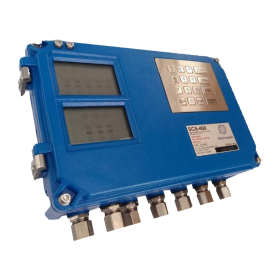
“sealed parcel delivery” system. The SCS-400 is housed in a combined Exd and Intrinsic safe enclosure, which has approximate dimensions of 347mm x 226mm x 91mm. Four M10 bolts secures the SCS- 400 onto the vehicle. -
Page 5: Exd
Manager’s site rules and guidelines to be followed to install equipment. b) Refer to Installation drawings for the flameproof dimensions and correct wiring. c) Inspection of the FLP-100 Enclosure (SCS-400) should be performed prior to powering of the system. -
Page 6: Intrinsic Safe
7. The BR2330 coin cell is not replaceable. 8. Only a Metermatic BBU-500 can be used in the SCS-400 system, replacement may only take place in a Safe Area. This is not a user replaceable battery. 9. The certification of this equipment relies upon the following materials used in its construction: ... -
Page 7: Scs-400
SCS-400 Installation Manual 2.4. SCS-400 a) The installed location height of the unit should permit easy viewing of the display, and provide convenient access to the keypad and the M16 Exd Antenna Bush assembly located on the top of the enclosure. -
Page 8: Installation
SCS-400 Installation Manual 3. Installation 3.1. SCS-400 Installation Block Diagram Rev 3 P a g e... -
Page 9: Scs-400 All Connections
SCS-400 Installation Manual 3.2. SCS-400 All Connections 400m A 125mA 80mA 125mA 315mA 40m A TEST POINTS G ND TP1 TP2 TP3 40m A TP4 TP5 TP6 TP7 VOLTAGE: 40m A 6.2V 40m A 3.3V 40m A 100mA 100mA 100mA... -
Page 10: Input Power (Connector J1)
Failure to do this will invalidate the IS certification. The SCS-400 is protected by a 5A internal fuse (F1). It is recommended to connect an additional 3A inline fuse on the positive (+) line from the vehicle battery. Install this fuse after the isolator switch as shown below. -
Page 11: Aux Battery (Connector J2)
Min Voltage = 16VDC Charge time = 3.5hours Note: The SCS-400 will not operate when the battery voltage is below 16V Only the Metermatic BBU-500 may be connected to these terminals. The BBU-500 can only be replaced when no explosive atmosphere is present. -
Page 12: Rs232 / Rs 485 (Connector J4)
Installation Manual 3.6. RS232 / RS 485 (Connector J4) The SCS-400 can interface to communication devices (Printer or On Board Computer) via connector J4. The port can be configured For RS232 or RS485 by using the jumper settings JP1 – JP4. -
Page 13: Rs232 / Gsm (Connector J5)
3.8. Gantry Permissive Interface (Connector J7) The overfill status of the vehicle is transmitted to the Gantry via the GPI connections on the SCS-400. It is important not to exceed the safety parameters of J7 (see section J7 GPI Interface [Ex ia]) Failure to do this will invalidate the IS certification. -
Page 14: Wire Sensor Interface (Connector J8)
5 Wire Sensor Interface (Connector J8) The SCS-400 interfaces to 5 Wire Overfill Sensors that comply with EN13922. The SCS-400 can interface to a maximum of 10 x 5 wire sensors (10-compartment vehicle). It is important not to exceed the safety parameters of J8 (see section... -
Page 15: Canbus Interface (Connector J9)
When wiring the CAN Bus, the objective is to maintain the shortest possible cable length connecting all sensors. Examples of CAN BUS wiring is shown below. The first example is when the SCS-400 is mounted in front of the API’s and the second example is when the SCS-400 is mounted behind the API’s. - Page 16 SCS-400 Installation Manual Rev 2 P a g e | 13...
- Page 17 SCS-400 Installation Manual Rev 2 P a g e | 14...
- Page 18 SCS-400 Installation Manual Rev 2 P a g e | 15...
-
Page 19: Io Interface (Connector J10)
Installation Manual 3.11. IO Interface (Connector J10) The SCS-400 has a single Intrinsically Safe output that can be used to switch a certified relay or solenoid. Alternatively, it can be used as a permissive signal to a certified OBC. The SCS-400 has a single Intrinsically Safe input that can be switched from a certified contact. -
Page 20: Proximity Interface (Connector J11)
SCS-400 Installation Manual 3.12. Proximity Interface (Connector J11) The SCS-400 can interface to two certified Namur Proximity switches or Current switches. It is important not to exceed the safety parameters of J11 (see section J11 – Proxy Interface [Ex ia]). Failure to do this will invalidate the IS certification. -
Page 21: Wire Sensor Interface (Connector J12)
SCS-400 Installation Manual 3.13. 2 Wire Sensor Interface (Connector J12) The SCS-400 can interface to 12 x 2 wire retain sensors. It is important not to exceed the safety parameters of J12 (see section J12 - 2 Wire Interface [Ex ia]). -
Page 22: Troubleshooting
SCS-400 Installation Manual 4. Troubleshooting 4.1. EXD Test Points TP1 = 24V. Related fuse – F1. TP2 = 23V – 24V. Related fuse – F1. TP3 = 6.2V – 6.4V. Related fuse – F16. TP4 = 12V. Related fuse – F1. -
Page 23: Is Test Points
SCS-400 Installation Manual 4.2. IS Test Points TP8 = 12V. Related Fuse – F4. TP9 = 5V – 6V. Related Fuse – F2. TP10 = 3.3V. Related Fuse – F5. TP11 = 11.2V – 11.5V. Related Fuse – F3. TP12 = 5V Related Fuse – F3. -
Page 24: Certification
SCS-400 Installation Manual 5. Certification 5.1. SCS-400 - 15.0026X Rev 2 P a g e | 21... - Page 25 SCS-400 Installation Manual Rev 2 P a g e | 22...
- Page 26 SCS-400 Installation Manual Rev 2 P a g e | 23...
-
Page 27: Annex To 15.0026X
5.2.1. Equipment The SCS400 is installed on a vehicle that enters hazardous areas. The SCS-400 has an aluminium enclosure with approximate dimensions of 347mm x 226mm x 91mm. It has an external cover and an internal flameproof (FLP-100) cover. Therefore, the enclosure comprises two chambers / enclosures. -
Page 28: Power To The Non-I.s. Electronics In The Flameproof Enclosure
Date: 2016-05-27 Electrical Apparatus: Safety and Control System SCS-400 The external cover covers all the internal electronics (outside the flameproof compartment), as well as the flameproof (FLP-100) cover. o A BBU-500 battery pack is attached to the flameproof enclosure cover. The battery is fully encapsulated and connected via a flying lead and a flameproof bushing B-BAT-EXD to a charging circuit inside the flameproof enclosure. -
Page 29: J8 - 5 Wire Interface [Ex Ia]
SCS-400 Installation Manual Certificate No.: IECEx ICS 15.0026X Issue: 0 Date: 2016-05-27 Electrical Apparatus: Safety and Control System SCS-400 5.2.1.3. J8 - 5 Wire Interface [Ex ia] = 11.76V = 235mA = 0.69W = 10uF = 5.1mH = 412uH/Ω Lo/Ro 5.2.1.4. -
Page 30: J11 - Proxy Interface [Ex Ia]
SCS-400 Installation Manual Certificate No.: IECEx ICS 15.0026X Issue: 0 Date: 2016-05-27 Electrical Apparatus: Safety and Control System SCS-400 5.2.1.6. J11 – Proxy Interface [Ex ia] = 5.88V = 12.38mA = 18.2mW = 600uF = 460mH = 15mH/Ω Lo/Ro 5.2.1.7. J10 – Output (pin 1 w.r.t 2) Interface [Ex ia] = 13.65V... -
Page 31: Jj8 - Dallas Tag Interface [Ex Ia]
SCS-400 Installation Manual Certificate No.: IECEx ICS 15.0026X Issue: 0 Date: 2016-05-27 Electrical Apparatus: Safety and Control System SCS-400 5.2.1.9. JJ8 – Dallas Tag Interface [Ex ia] = 5.88V = 248.4mA = 0.86W = 60uF = 2mH = 1.9mH/Ω Lo/Ro 5.2.1.10. -
Page 32: Special Conditions Of Use
5.2.2.2. Special conditions of use The following special conditions of use are applicable: The BBU-500 inside the SCS-400 enclosure may only be charged in the safe area. The circuit ground and local earth is electrically in contact with each other, which must be considered during installation. -
Page 33: Api, Bvs, Man, Ref - 15.0009X
SCS-400 Installation Manual 5.3. API, BVS, MAN, REF - 15.0009X Rev 2 P a g e | 30... - Page 34 SCS-400 Installation Manual Rev 2 P a g e | 31...
- Page 35 SCS-400 Installation Manual Rev 2 P a g e | 32...
-
Page 36: Annex To 15.0009X
SCS-400 Installation Manual 5.4. Annex to 15.0009X Certificate No.: IECEx ICS 15.0009X Issue: 0 Date: 2016-06-06 Sensors: API-400, BVS-100, MAN-400, REF-400 Electrical Apparatus: 5.4.1. Equipment 5.4.1.1. API-400: The API-400 sensor is intended to be mounted on bulk petroleum delivery vehicles to ensure a sealed parcel delivery system. -
Page 37: Man-400
SCS-400 Installation Manual Certificate No.: IECEx ICS 15.0009X Issue: 0 Date: 2016-06-06 Sensors: API-400, BVS-100, MAN-400, REF-400 Electrical Apparatus: 5.4.1.2. MAN-400: The MAN-400 manhole sensor is intended to be mounted on bulk petroleum delivery vehicles to ensure a sealed parcel delivery system. The MAN-400 has an integral lead fitted with a protective hydraulic hose. -
Page 38: Ref-400
SCS-400 Installation Manual Certificate No.: IECEx ICS 15.0009X Issue: 0 Date: 2016-06-06 Sensors: API-400, BVS-100, MAN-400, REF-400 Electrical Apparatus: An external stainless steel magnetic actuator probe/device is used to activate an internal Hall Effect sensor. = 8V = 3.119A (spark) -
Page 39: Conditions Of Certification
SCS-400 Installation Manual Certificate No.: IECEx ICS 15.0009X Issue: 0 Date: 2016-06-06 Sensors: API-400, BVS-100, MAN-400, REF-400 Electrical Apparatus: 5.4.2. Conditions of Certification 5.4.2.1. Special Conditions of use The MAN-400 shall only be mounted on its base such that the free surface of encapsulant is provided with mechanical protection, i.e.: screwed down.
Need help?
Do you have a question about the SCS-400 and is the answer not in the manual?
Questions and answers