Table of Contents
Advertisement
Advertisement
Table of Contents

Summary of Contents for Oaks Smart Access Control System
-
Page 2: Access Control System
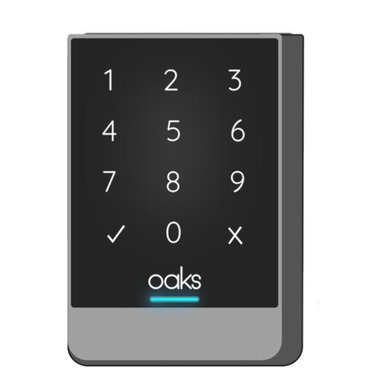
Inside View Introduction The Oaks Smart Access Control system is a cloud-based solution for tracking and managing both FOB and door code credentials. The Smart Access Panel can be used to control any access device that is operated by normally open/normally closed signal, provided the voltages are compatible. -
Page 3: Installation
Single Door Magnetic Lock ○ American Standard Electric Strike (Short Panel) ○ Rently Keyless Smart Home Hub Individual Components Instructions This section includes instructions for each component of the Oaks Smart Access Control System Continue to next page Page 3... -
Page 4: Control System
Metal Access Control System Installation Run a power cable to the location where the Metal Access Control System will be mounted. Remove screw from bottom of Metal Access Control System with provided torx wrench. Remove the mounting plate. Thread the cable attached to the Metal Access Control System through the hole in the mounting plate. -
Page 5: Power Supply
(continued) Wiring Diagram Installation Power Supply Controller Specifications Item Specification Input AC110 V 50Hz Output DC12 50VA Dimension 180mm X78m X 65mm (7in X 3in X 2.5in) Weight 1250g (2.75lb) Ambient Temp -20C°--- 55C° (-4F°---122F°) 30%-90% Page 5... -
Page 6: Lock Bracket
(Continued) Function This power supply controller can control electric locks by switching the signal from access controllers or power supply output DC12V directly. It can reduce overload controller, adjust electric lock to on or off mode, adjust the open delay time, open key. Wiring Diagram for Installation: Start by removing 2 silver screws to remove the power supply controller cover. -
Page 7: Magnetic Lock
Installation 1. Measure the gap between the door leaf and door frame. 2. Install the top bracket according to the diagram. Fix the screw, keep the screw head inside the U-shaped slot. 3. Put the rubber mounting plate and iron mounting plate into the U-shaped slot. (For easier installation, paste double-sided adhesive between the rubber mounting plate and the U-shaped slot.) 4. - Page 8 Main Components Diagram Double Door Single Door Disassemble Procedure Disassemble the cover and band before installing the lock. Standard Mounting Method 1. Use the supplied template to determine the correct location and size of mounting holes for both the door and frame header. Ensure that the door opens away from the Maglock. In the case of a single door, the Maglock is positioned as close as possible to the vertical section of the door jamb.Drill door and frame as indicated.
-
Page 9: American Standard
3. Using a hammer, lightly tap both roll pins into the armature plate until they are secure. 4. Before installing the Hex Nut, the hole in the door may need to be drilled or tapped. Refer to the previous page for this information. Using the components shown in the image to the right, mount the armature to the door. - Page 10 Wiring Diagram Scenario A: Oaks Smart Access Control System with Magnetic Lock Scenario B: Oaks Smart Access Control System with Electric Strike Page 10...
-
Page 11: Post Installation
To ensure that there was wiring was done correctly, please press the exit button to see if the single door magnetic lock releases for a few seconds. If the test is failed, please reexamine the installation and wiring of the Oaks Smart Access Control System. - Page 12 End User Guide Section for Real Estate Operators and Managers How does a Manager set up resident access? Make sure the access panels are assigned to Common Area assets. Create a common access community, including both the common area assets and the residents’...
- Page 13 How does a Manager add a staff fob or code? Go to the staff section, and click new staff/code or click edit on an existing staff/code. Make sure both code and fob are enabled in the checkboxes. Select the fob you want to add, and input its number written beneath the barcode into the fob field. Enter or randomly generate the 6 digit code you want the staff to have.
- Page 14 How can a manager check the activity log? Click on the asset that has the device you want to see Click on the activity log tile Click “fetch logs” to get the most recent information Wait a couple minutes, then click the “view all” button. You can also use the device dropdown to select specific panels you want to review, if more than one are attached to the same asset.
- Page 15 Section for Residents Residents and Codes ● Resident’s are created with default codes, which are automatically pushed to all common areas within their assigned community. ● If a resident desires to edit their own code, or create additional codes that work on their own home, these changes also push to the common areas.
- Page 16 How can a resident unlock via the app? 2. Select the desired lock to 3. Tap on unlock to unlock Log onto the app interact with it. selected lock. Page 16...
- Page 17 FCC Warning Statement Changes or modifications not expressly approved by the party responsible for compliance could void the user’s authority to operate the equipment. This equipment has been tested and found to comply with the limits for a Class B digital device, pursuant to Part 15 of the FCC Rules. These limits are designed to provide reasonable protection against harmful interference in a residential installation. This equipment generates uses and can radiate radio frequency energy and, if not installed and used in accordance with the instructions, may cause harmful interference to radio communications. However, there is no guarantee that interference will not occur in a particular installation. ...
Need help?
Do you have a question about the Smart Access Control System and is the answer not in the manual?
Questions and answers