Table of Contents
Advertisement
Quick Links
And can't be transmitted to someone also with out prior authorisation
In conformity with the European directive 94/9/CE-ATEX
SATAM
Usine de Falaise – Avenue de Verdun – B.P. 129 – 14700 FALAISE – France
Tél. : +33 (0)2 31 41 41 41
Fax : +33 (0)2 31 40 75 61
SIRET 495 233 124 000 17
CODE APE 2813 Z
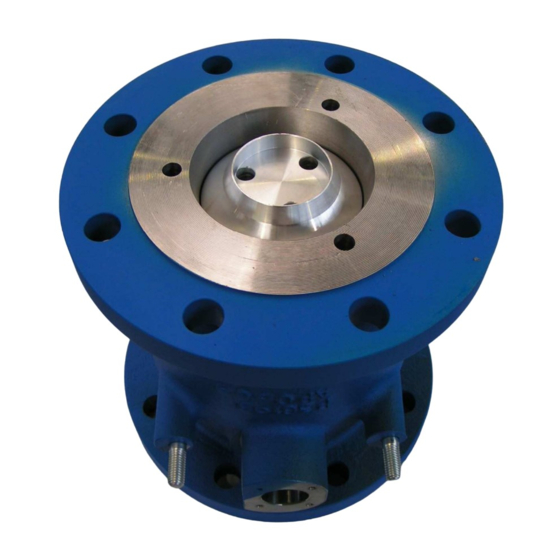
STOP-VALVE TYPE XAD 36
Disassembly and reassembly
U508103-e– Révision 3 – 17 February 2009
This document consists of
This document is the property of SATAM
SATAM may modify this document without prior notice
9
pages, including the flyleaf
Siège Social : Paris Nord II – Bât. Le Gauguin – 47, allée des Impressionnistes
B.P. 85012 – Villepinte – 95931 Roissy C.D.G. Cedex - France
Tél. : +33 (0)1 48 63 02 11
Fax : +33 (0)1 49 38 41 01
SA au capital de 6 037 000 € – RCS Bobigny B 495 233 124
SIRET 495 233 124 000 17 – Code APE 2813 Z – N° TVA : FR 48 495 233 124
Advertisement
Table of Contents

Summary of Contents for SATAM XAD 36
- Page 1 This document is the property of SATAM And can’t be transmitted to someone also with out prior authorisation SATAM may modify this document without prior notice In conformity with the European directive 94/9/CE-ATEX SATAM Siège Social : Paris Nord II – Bât. Le Gauguin – 47, allée des Impressionnistes Usine de Falaise –...
-
Page 2: Table Of Contents
SUMMARY DISASSEMBLY OF THE STOP-VALVE....................3 Preparation to the disassembling......................3 DISASSEMBLY OF STOP-VALVE........................4 Disassembly of the stop-valve..........................5 REASSEMBLY OF STOP-VALVE ........................6 REASSEMBLY OF THE VALVE ........................7 Clean the body of the valve ........................7 Assembly the piston ( Fig.1 )........................7 Prepare the sleeve (Fig.2)........................ -
Page 3: Disassembly Of The Stop-Valve
SERVICE AND REPAIR OF STOP-VALVE TYPE XAD 36 1 DISASSEMBLY OF THE STOP-VALVE Preparation to the disassembling - Electric insulation of the loading station. - Hydraulic insulation of the station. - Drain of the strainer. - Disassembly the case of electrical order : Disassembly the hood. -
Page 4: Disassembly Of Stop-Valve
DISASSEMBLY OF STOP-VALVE Fig.1 Fig.4 Fig.2 Fig.3 Fig.5 Fig.6 Le 17/02/09 U508103-e Révision : 3... -
Page 5: Disassembly Of The Stop-Valve
Disassembly of the stop-valve - Disassembly the no return valve (Fig.1). - Remove the seat of valve.(a) - Pull out the valve (b) and the spring.(c) - Disassembly the axle (Fig.2). - Notice the lever of order and pull out the pin. - Remove the lever of order.(a) - Dismantle 4 screws of the cover (b) Collect the o’ring.(c) -
Page 6: Reassembly Of Stop-Valve
REASSEMBLY OF STOP-VALVE Fig.1 Fig.2 Fig.3 Fig.4 Fig.5 Le 17/02/09 U508103-e Révision : 3... -
Page 7: Reassembly Of The Valve
REASSEMBLY OF THE VALVE Clean the body of the valve - To clean the interior of the body with solpar, gasoline or gas oil. Assembly the piston ( Fig.1 ) - Assembly the gasket (1) with piston (2). To slacken the joint with hot water. - Assembly the packing (3) on the piston (2) by fixing the nose of the piston (4) by 3 screws. - Page 8 REASSEMBLY OF STOP-VALVE Fig.6 22 23 Fig.7 Fig.8 Le 17/02/09 U508103-e Révision : 3...
-
Page 9: Assembly The System Of Order ( Fig.6, 7 And 8 )
Assembly the system of order ( Fig.6, 7 and 8 ) - Assembly 2 o’rings (18) on the axle (19). to make sure that there are no arrises on the axis which can cause the deterioration of the joints. - Put grease on the hole of the body. - Installation of the lever of order (20).