Table of Contents
Advertisement
Quick Links
Advertisement
Table of Contents

Subscribe to Our Youtube Channel
Related Manuals for maxxess eMAX-LP1502


Summary of Contents for maxxess eMAX-LP1502
- Page 1 INTELLIGENT CONTROLLER Installation Guide and Specifications This device complies with FCC Part 15, Class A Specifications. The device meets CE Specifications, and is RoHS Certified. February 2019 This device is UL 294 Recognized.
-
Page 2: Table Of Contents
Paragraph Title Page No. General …………………………………………………………………………………………….. 3 eMAX-LP1502 Hardware ……………………………………………….……………………...… 4 eMAX-LP1502 Wiring and Setup …………………….……………………………………...… 5 Bulk Erase Configuration Memory ……………………………………………………………. 7 Input Power, Cabinet Tamper, UPS Fault Wiring …………………..……………………….. 8 Communication Wiring …………………………………………………………………………. 8 Reader Wiring …………………………………………………………………………………….. 8 Input Circuit Wiring ………………………………………….………………………………….. -
Page 3: General
(2) multi-dropped Readers in an IN/OUT Reader configuration, resulting in the support for up to four (4) Readers. The eMAX-LP1502 provides four (4) Form-C Contact relay outputs which may be used for door strike control or alarm signaling. The relay contacts are rated at 5A @ 30Vdc resistive on the Normally-Open (N/O) contacts, and 3A @ 30Vdc resistive on the Normally-Closed (N/C) contacts, dry contact configuration. -
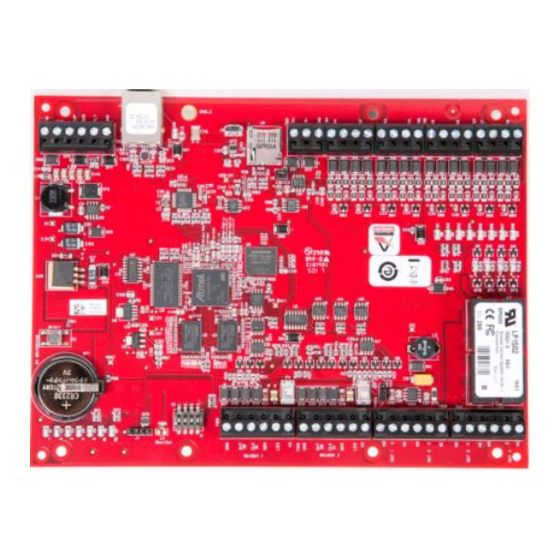
Page 4: Emax-Lp1502 Hardware
Hardware: BATTERY: BR/CR2330 S2: RESET REPLACE ANNUALLY SWITCH Ø.156 [3.96] 8 PLACES 3V BR/CR2330 .50 [12.70] STATUS LEDs J2: ETHERNET JACK 2.00 [50.80] S1 : DIP SWITCHES EARTH GROUND J6: Micro USB JACK J8: microSD CARD 8.00 [203.20] 3.00 [76.20]... -
Page 5: Emax-Lp1502 Wiring And Setup
Wiring and Setup: CONNECTION CONNECTION TB1-1 TB8-1 Power Fault Reader 1 GND: Ground TB1-2 TB8-2 DAT/D0: Data/Data 0/TR- (A) Input See note 1 TB1-3 TB8-3 CLK/D1: Clock/Data 1/TR+ Cabinet (B) See note 1 TB1-4 TB8-4 Tamper Input BZR: Reader Buzzer... - Page 6 Jumpers and Jacks: The eMAX-LP1502 processor hardware interface is configured using jumpers to setup the reader port power and end of line termination. JUMPERS SET AT DESCRIPTION Factory Use Only 10-Base-T/100Base-Tx Ethernet Connection (Port Factory Use Only RS-485 EOL Terminator is Off RS-485 EOL Terminator is On Micro USB Port (2.0)
-
Page 7: Bulk Erase Configuration Memory
2. Apply power to the eMAX-LP1502 board. LED 1 on for up to 15 seconds while board boots up. 3. After the eMAX-LP1502 boots up, watch for LEDs 1 & 2 and 3 & 4 to alternately flash at a 0.5 second rate. -
Page 8: Input Power, Cabinet Tamper, Ups Fault Wiring
➢ RS-485 signaling requires two 2-conductor cables. Use one cable for power (18 AWG) and one cable for communication (24 AWG Twisted Pair, with drain wire and shield). J7 – Reader Power Select If the input voltage to the eMAX-LP1502 is 12 Vdc, jumper J7 MUST be in the PASS position. February, 2019 eMAX-LP1502-Man... - Page 9 NORMALLY OPEN CONTACT * Typical Unsupervised F/2F Reader Typical Supervised F/2F Reader Jumper D1 to LED on supervised F/2F readers * Inputs on supervised F/2F readers may be unsupervised or supervised (supervised shown). February, 2019 eMAX-LP1502-Man Page 9 of 20...
-
Page 10: Input Circuit Wiring
Input Circuit Wiring: The eMAX-LP1502 provided 8 inputs that are typically used to monitor door position, request to exit, or alarm contacts. Input circuits can be configured as unsupervised or supervised. When unsupervised, reporting consists of only the open or closed states. -
Page 11: Relay Circuit Wiring
Door lock mechanisms can generate feedback to the relay circuit that can cause damage and premature failure of the relay plus affect the operation of the eMAX-LP1502. For this reason, it is recommended that a diode be used to protect the relay. Wire should be of sufficient gauge to avoid voltage loss. -
Page 12: Status Leds
Relay K3: ON = Energized Relay K4: ON = Energized Note : If this input is defined, every three seconds the LED is pulsed to its opposite state for 0.1 seconds, otherwise, the LED is off. February, 2019 eMAX-LP1502-Man Page 12 of 20... -
Page 13: Specifications
Cable requirements: Power and Relays: 1 twisted pair, 18 to 16 AWG Ethernet: CAT-5, minimum RS-485: (I/O Device Port): 1 twisted pair, shielded, 120 ohm impedance, 24 AWG, 4,000 ft. (1,219 m) max. February, 2019 eMAX-LP1502-Man Page 13 of 20... - Page 14 8 in. (203.2 mm) W x 6 in. (152.4 mm) L x 1 in. (25 mm) H Weight: 9 oz. (255 g) nominal, board only UL294, 6 edition Performance Levels: Feature Level Standby Power Endurance Line Security Destructive Attack These specifications are subject to change without notice. February, 2019 eMAX-LP1502-Man Page 14 of 20...
-
Page 15: Warranty And Liability
This product is not intended for, nor is rated for operation in life-critical control applications. Maxxess Systems is not liable under any circumstances for loss or damage caused by or partially caused by the misapplication or malfunction of the product. Maxxess Systems liability does not extend beyond the purchase price of the product. -
Page 16: Appendix A - Configuring The Emax-Lp Controllers
First Click on “ Details “, which will tell you that your PC does not recognize the Web Pages’s Security Certificate. This is Normal. Then click on “ Go on to the webpage “. February, 2019 eMAX-LP1502-Man Page 16 of 20... - Page 17 Login using username ‘admin’ and password’ password’. The following message will appear if you FAILED to turn Switch #1 to ON, or if 5 minutes have elapsed since turning switch #1 to ON. February, 2019 eMAX-LP1502-Man Page 17 of 20...
- Page 18 Browse to the Users link and add a user. If the new user details are ever lost, the controller dipswitch S1 may be used to re-enable the default user. Click on the Network page to configure the IP parameters February, 2019 eMAX-LP1502-Man Page 18 of 20...
- Page 19 Configure the required IP Address, Subnet Mask, Default Gateway (as applicable) for the eMAX-LP1502. If using Redundant host communication, you will need to configure the Interface 2 (NIC2) parameters. To SAVE, Click on “Accept” button, then select the ‘Apply Settings’ button Then click the “Apply Settings, Reboot”...
- Page 20 If you wish to proceed, check both of the check boxes, then click on the “Yes” box to proceed. You should see a message that “The Board is Restarting”. And a selection box to CLOSE the window. February, 2019 eMAX-LP1502-Man Page 20 of 20...
Need help?
Do you have a question about the eMAX-LP1502 and is the answer not in the manual?
Questions and answers