Table of Contents
Advertisement
Quick Links
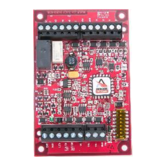
SINGLE DOOR CONTROLLER
Installation Guide and Specifications
This device complies with Part 15 of the FCC Rules.
Operation is subject to the following two conditions:
(1) This device may not cause harmful interference
(2) This device must accept any interference received,
including interference that may cause undesired operation.
This device meets CE Specifications, and is RoHS Certified.
This device is UL 294 Recognized.
eMAX-MR50
–
Series 3
FEBRUARY 2018
Advertisement
Table of Contents

Subscribe to Our Youtube Channel
Related Manuals for maxxess 3 Series


Summary of Contents for maxxess 3 Series
- Page 1 eMAX-MR50 – SINGLE DOOR CONTROLLER Series 3 Installation Guide and Specifications This device complies with Part 15 of the FCC Rules. Operation is subject to the following two conditions: (1) This device may not cause harmful interference (2) This device must accept any interference received, including interference that may cause undesired operation.
-
Page 2: Table Of Contents
TABLE OF CONTENTS Paragraph Title Page No. 1. General …………………………………………………………………………………………….. 2. eMAX-MR50 Hardware ……………………………………..…………….………….………...… 3. Reader Wiring ……………………………………………………………………………………. 4. Door Strike/Lock Relay Wiring ……………………………….……………………………….. 5. Communication Wiring ……………………………………….……………………………….. 6. Dip Switch Configuration …………….……………………………….………….…………… 7. Status LEDs ………………………………………………………………..……………………. 8. Specifications …………………………………………………………………...………………. Warranty and Liability ……………………………………………………………………………….. -
Page 3: General
eMAX-MR50 SINGLE DOOR CONTROLLER Series 3 1. General: The eMAX-MR50-S3 Single Door Controller provides a solution for interfacing to a TTL (D1/D0, Clock/Data), F/2F or RS-485 Reader-type devices, and associated door hardware. It also provides for tri-stated LED control and buzzer control. Two Form-C contact relay outputs may be used for door lock control or alarm signaling. Two inputs are provided that can be used for monitoring the door contact and request to exit device. -
Page 4: Reader Wiring
3. Reader Wiring: The reader port supports a reader with TTL (D1/D0, Clock/Data), F/2F, or 2-wire RS-485 signaling. **Refer to the reader manufacture specifications for cabling requirements. In the 2-wire LED mode, the buzzer output is used to drive the second LED. Reader port configuration is set via the host software. D1/CLK/TR+ D1/CLK/TR+ D0/DAT/TR-... -
Page 5: Door Strike/Lock Relay Wiring
INSTALL ON LAST UNIT OF COMMUNICATION LINE The eMAX-MR50-S3 Controller communicates to a Maxxess EP Series Intelligent Area Controller (EP2500 for example) via a half-duplex multi-drop 2-wire RS-485 interface. The total cable length is limited to 4,000 feet (1,219 meters). Shielded cable of 24 AWG with characteristic impedance of 120 ohm is specified for the 2-wire RS-485 interface. -
Page 6: Dip Switch Configuration
6. DIP Switch Configuration: Switches 1 to 5 select the device address. Switch 6 and 7 select the communication baud rate. Switch 8 enables encrypted communication. All other configuration settings are set via host software. Defaults are address 0 and baud rate 38,400. SELECTION Address 0 Address 1... -
Page 7: Status Leds
7. Status LEDs: Power-up: All LED’s OFF Initialization: Once power is applied, initialization of the module begins The D1 LED is turned ON at the beginning of initialization Run time: After a successful initialization, the LEDs have the following meanings: D1 LED: Heartbeat and On-Line Status: Off-line: 1 second rate, 20% ON, 80% OFF On-line: Non-encrypted communication: 1 second rate, 80% ON, 20% OFF... -
Page 8: Specifications
8. Specifications: Revision E assembly: The eMAX-MR50-S3 Interface is for use in low voltage, class 2 circuits only. Primary Power: 12 to 24 Vdc ± 10%, 150 mA maximum (plus reader current) Outputs: Two Form-C contact relays: K1: Normally open contact (NO) contact: 5 A @ 30 Vdc resistive Normally closed contact (NC) contact: 3 A @ 30 Vdc resistive K2: 1 A @ 30 Vdc resistive Inputs:... -
Page 9: Warranty And Liability
This product is not intended for, nor is rated for operation in life-critical control applications. Maxxess Systems, Inc. is not liable under any circumstances for loss or damage caused by or partially caused by the misapplication or malfunction of the product. Maxxess System, Inc. liability does not extend beyond the purchase price of the product.
Need help?
Do you have a question about the 3 Series and is the answer not in the manual?
Questions and answers