Advertisement
Quick Links
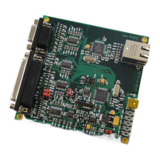
CPU5A
Card size 100x100mm
3 or 4 axes interpolation, 125 KHz step frequency.
Standard CNC outputs (TOOL, TOOL SPEED: PWM / 0-10V, Flood coolant, Mist coolant, AUX1, Watchdog)
Standard CNC inputs (4 Home inputs, Probe, Spindle sensor, Run, Pause, E-Stop, Hand wheel)
Powered by USB or +5V external.
4 Axes + USB + Ethernet (USBCNC_CPU5A4E)
3 Axes + USB (USBCNC_CPU_5A3) ... 4 Axes + USB (USBCNC_CPU_5A4)
Connector
Signal
Connector
Signal
Advertisement

Summary of Contents for EdingCNC CPU5A4E
- Page 1 CPU5A Card size 100x100mm 3 or 4 axes interpolation, 125 KHz step frequency. Standard CNC outputs (TOOL, TOOL SPEED: PWM / 0-10V, Flood coolant, Mist coolant, AUX1, Watchdog) Standard CNC inputs (4 Home inputs, Probe, Spindle sensor, Run, Pause, E-Stop, Hand wheel) Powered by USB or +5V external.
- Page 2 1: OUT TOOL 1: IN RUN 25P SUBD - FEMALE 2: OUT DIR1 9P-SUBD-FEMAILE 2: IN PAUSE 3: OUT STEP1 3: OUT MIST 4: OUT DIR2 4: OUT AUX1 5: OUT STEP2 5: IN HANDWHEEL A 6: OUT DIR3 6: IN HANDWHEEL B 7: OUT STEP3 7: +5V 8: OUT DIR4...
- Page 3 100 mA max current. PWM frequency 5 Khz Charge pump frequency 10 Hz (LED4) See also the manual about how to use an open collector output. 0..10 Volt output 10 mA for VFD control...
- Page 4 Jumper settings Jumpers The yellow marked jumpers are the only ones interesting to you. The others should be left untouched. Lower left (USBPWR) is set if the board is powered by the USB voltage. Remove if you want to power externally. External POWER can be applied on the SUBD 25 connector (PIN 20-21, 22-25).
- Page 5 This jumper selects the signal on PIN 17 of the DB25. Jumper to the right => PWM out. Jumper to the left => 0-10 Volt out. This jumper controls the watchdog output at PIN 16 of the SUBD 25. The upper jumper controls the output being NPN or PNP.
- Page 6 This GREEN LED shows the state of the Watchdog. ON => Safe OFF => Not Safe...
- Page 7 Connection to the stepper motor or servomotor drive EXAMPLE1 - USE WATCHDOG TO AMPENABLE FOR LEADSHINE DRIVE (POSITIVE PULSE CONNECTION) The Leadshine drives are OFF when the input is driven, it is opposite of what most of us expect. Upper jumper to the left (PNP), Lower to the right (ON-SAFE) Positive pulse connection does not need the +5V, that is the difference with negative pulse connection.
- Page 8 So the first selected axis in the setup is connected to STEP1/DIR1 the next to STEP2/DIR2 etc. Connection of the inputs HOME - ESTOP - PAUSE - RUN - HANDWHEEL - SPINDLE-SENSOR INDUCTIVE HOME NPN Type SENSORS SIMPLE HOME SWITCH Normally Open Type HomeInputSenseLevel = 0 Normally Closed Type...
- Page 9 Handwheel +5 Volt handwheel Spindle sensor Ask your dealer This is required for Lathe Thread cutting Probe A probe can be a normally open or normally closed switch. Connection of the outputs TOOL (Kress) - VFD - FLOOD - MIST -AUX1 TOOL FLOOD MIST AUX This is the way I recommend, SOLID STATE RELAY...
-
Page 10: Bootloader Mode
TOOL FLOOD MIST AUX Standard relays cause a lot of RELAY EMV noise. EMV noise can disturb the USB communication. I recommend to use standard relay's only for low power. Never for get to apply a anti parallel diode of 100 - 200 volt / 1 - 2 Amp. - Page 11 Upgrading USBCNC_CPU5A3 to USBCNC_CPU5A4 If you have bought a CPU5A3 and want to use the 4th axis, it is possible to upgrade. Via the 2nd setup page in the USBCNC software, see explanation below: CPUOPT: This is special for CPU5A. This button allows to add the 4th axis function on a CPU5A3.
- Page 12 These are the steps to follow: In the dialog check the "enable axis 4" checkbox, enter tour name and press get request code: Send the request code to the supplier. Copy and paste it into an email and send it to your USBCNC supplier. To do this double click the code, press ctrl-c, in your e-mail press control-v.
Need help?
Do you have a question about the CPU5A4E and is the answer not in the manual?
Questions and answers