
Related Manuals for Bob Long Technologies Intimitador G6R


Summary of Contents for Bob Long Technologies Intimitador G6R
- Page 1 Bob Long Technologies 209-293-4440 www.boblongdirect.com CAUTION: READ ALL WARNINGS BEFORE USING OR ATTEMPTING ANY WORK ON YOUR MARKER. SHOULD YOU BE UNSURE AT ANY POINT, STOP AND SEEK PROFESSIONAL SUPPORT.
-
Page 2: Table Of Contents
Table of Contents Warning ........................................3 Warranty ........................................3 Introducing the G6R ..................................4 Ready for the Field ..................................4 Trigger Adjustment and Maintenance ............................5 Maintaining the Eyes and Detents ............................6 Maintaining the HPR (In-Line-Regulator)..........................7 Maintaining the LPR ..................................8 Setting Pressures Using the Pressure Tester ........................9 Maintaining the bolt .................................. -
Page 3: Warning
ASTM standards F1777-97. Ensure you read the entire instruction manual before operating your marker. Bob Long Technologies warrants our paintball markers to be free from defect in materials and Warranty workmanship for a period of 1 year from purchase date. This warranty will only be honored for the initial retail purchaser and is non-transferable. -
Page 4: Introducing The G6R
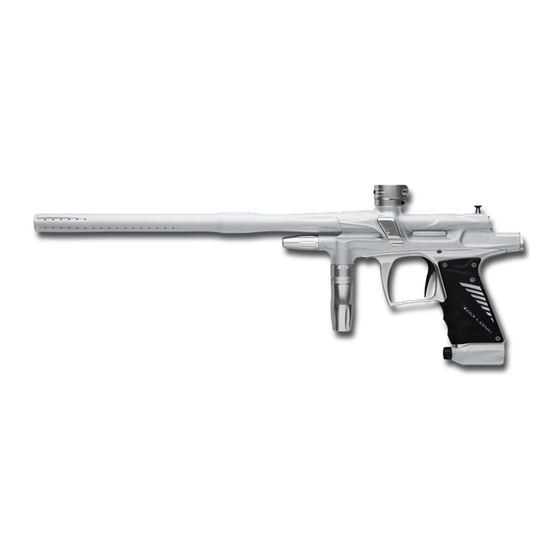
The sixth generation Intimidator platform, G6R, brings new advances to the stacked tube poppet Introducing the G6R valve marker. These advances include the front/rear split body and internally routed, macroline free air channels. The front/rear split enables more choices in milling, internal air routing, and weight reduction than standard one piece designs. -
Page 5: Trigger Adjustment And Maintenance
The G6R comes with a roller bearing trigger which you can adjust for the feel which is most Trigger Adjustment and Maintenance comfortable with your style of play. To simplify maintenance the trigger can be removed from the marker without requiring the removal of the grip frame. 1. -
Page 6: Maintaining The Eyes And Detents
In the event of a chopped ball or debris in the breach, the eyes in your G6R may need cleaning. The Maintaining the Eyes and Detents most common ways for debris to enter the ball chamber is through the hopper when using a rapid/ speed feed type system. -
Page 7: Maintaining The Hpr (In-Line-Regulator)
Your G6R comes equipped with the best regulators on the market. To ensure the highest Maintaining the HPR (In-Line-Regulator) consistency and the maximum flow possible, we recommend that you clean and lubricate them according to the maintenance schedule or whenever you encounter inconsistency. The regulators typically perform flawlessly for many cases of paint before requiring any maintenance. -
Page 8: Maintaining The Lpr
The LPR contains both right and left hand threaded parts. Following the disassembly instructions Maintaining the LPR below will prevent damaging your marker. 1. Unscrew the LPR assembly from the front of the marker. Remember Lefty Loosy and Rightie Tightie. If you have trouble loosening the LPR use one of those things your mom has in the kitchen to help grab jar lids. -
Page 9: Setting Pressures Using The Pressure Tester
Setting the pressures after regulator service is the best method to get your marker performing well. Setting Pressures Using the Pressure Tester The LPR controls marker cycling and contributes to noise and kick experienced when firing the marker. Setting the LPR too low will result in problems with consistency. The HPR controls the velocity of the marker. -
Page 10: Maintaining The Bolt
1. De-gas the marker and insure that there 7. Reinsert the bolt into the marker Maintaining the bolt are no paintballs in the breech or barrel ensuring to place the pin into the of the marker. groove of the ram. 2. -
Page 11: Maintaining The Poppet Valve
Maintaining the Poppet Valve Poppet valve maintenance is rarely required and incorporates parts of previous maintenance steps. Accessing the Poppet 1. Begin by removing the bolt, back cap, and ram. 2. Remove the eye cover screws, detents, and the eye PCB retaining screws. -
Page 12: Cleaning The Poppet And Reassembly
Once all the parts are disassembled and cleaned, the poppet can be lubricated then the marker Cleaning the Poppet and Reassembly reassembled. 1. Clean debris and excess grease from the poppet surface then inspect and grease the poppet o-ring. Replace the o-ring if any nicks or deformations are visible. -
Page 13: Grip Frame Removal
For most maintenance the grip frame doesn’t require removal. However, in case of excessive paint Grip Frame Removal on the grip frame, excessive curiosity, or excessive free time, here is how to go about doing it moderately sanely. The trigger can be removed any time during this process before removing the front and rear frame screws. -
Page 14: O-Rings And Fasteners
O-Rings and Fasteners O-rings Part Name Specifications Quantity Mainbody Rear to Manifold 1 x 2mm Buna Durometer 70 Grip Frame to Manifold 1 x 4mm Buna Durometer 70 ASA to Grip Frame 1 x 4.5mm Buna Durometer 70 Manifold to Mainbody Front 1 x 5mm Buna Durometer 70 Manifold to Mainbody Rear 1 x 8mm Buna Durometer 70... -
Page 15: Fasteners
Fasteners Part Name Specifications Quantity Bottom PCB to Grip frame M2 x 4 Pan Head Machine Screw 18-8 SS Top PCB to Grip Frame M2 x 10 Pan Head Machine Screw Solenoid to Solenoid Manifold M2 x 20mm Flat Head Machine Screw 18-8 SS Left &... -
Page 16: O-Ring Size Table
O-Ring Size Table 1x2mm 1x4mm 1x4.5mm 1x5mm 1x8mm 1x13mm 1x15mm 1x18mm 1.5x20mm CAUTION: READ ALL WARNINGS BEFORE USING OR ATTEMPTING ANY WORK ON YOUR MARKER. SHOULD YOU BE UNSURE AT ANY POINT, STOP AND SEEK PROFESSIONAL SUPPORT. -
Page 17: Q&A
If necessary back out the trigger activation set screw ½ turn. 2. Q: Where can I get an o-ring kit? A: Bob Long Technologies and authorized resellers have o-ring and parts kits available. 3. Q: What is the recommended dwell setting? A: Dwell should be at 6 from the factory. - Page 18 16. Q: I need to ship my marker in for technical support – what is the address? A: The address varies depending on whether shipping by postal service or another method. Bob Long Technologies USPS/postal shipping: P.O. Box 457...
-
Page 19: Troubleshooting Guide
Marker will not turn on out of the box -Ensure that the battery that you’re using in your new Troubleshooting Guide marker is a high quality alkaline 9 volt. -Verify that your battery is correctly oriented (matching with the correct terminals), and that it is making firm contact with the prongs on the circuit board. - Page 20 Marker does not gas up after tank is -Verify that the pin valve on your tank is outputting connected pressure to the regulator—some tanks will not work properly with certain ASAs. -Attempt gassing up the marker with another tank to see if this remedies the issue.
- Page 21 Marker fires more than one shot per - Verify that your trigger has the spring installed and that pull, or has trigger bounce it is properly seated - Verify that your marker is in semi-automatic mode - Raise your marker’s debounce level, and make sure that your trigger activation point is not too short.
Need help?
Do you have a question about the Intimitador G6R and is the answer not in the manual?
Questions and answers