Table of Contents
Advertisement
Quick Links
Advertisement
Table of Contents

Related Manuals for TVC GFM2


Summary of Contents for TVC GFM2
- Page 1 GFM2 Gas Flow Meter 2 including Analysis Model Instruction Manual V2.0 The Validation Centre (TVC) Limited Unit 15, Brinell Way, Harfreys Industrial Estate, Great Yarmouth, Norfolk, NR31 0LU, UK. +44 (0)1493 443800 sales@tvcalx.co.uk www.tvcalx.co.uk...
-
Page 2: Table Of Contents
Transferring Logged Files into MS Excel Reports 11 2.6.1 Surge File Example Removing Logged Files Changing Measured Units or Date and Time GFM2 Analysis Edition (Optional) Field Calibration Operational Flow Charts Flow Chart 1 Flow Chart 2 Flow Chart 3... -
Page 3: Description
Thread adaptors (male and female; 3/8” and 1/4”) Quick-fit extensions with thread adaptors (male and female; 3/8” and 1/4”) Nozzles (16mm, 19mm and 22mm; only one pictured above) Nozzle extension hose GFM2 to PC USB interface lead GFM2 to TVC Welding Data Logger interface lead (optional) -
Page 4: Connectors And Controls
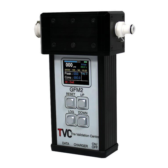
Connectors and Controls Quick-fit flow inlet Quick-fit flow outlet Display screen ‘Reset’ button (reset peak gas flow value) ‘Log’ button ‘Up’ button ‘Down’ button Close up view of quick-fit flow inlet and outlet... -
Page 5: Operational Instructions
Operational Warnings The following MUST be read before attempting to use the GFM2: 1 The GFM2 is designed for use on Inert Arc Welding Shielding and Back Purging gases ONLY. The GFM2 is designed for use with Inert Welding gases. NEVER attempt to monitor Fuel gases or Oxygen with the GFM2. -
Page 6: Powering Up The Unit
Powering Up the Unit Switch the On / Off button to the ‘On’ position. The GFM2 LCD will illuminate and the software version number together with the model type will be displayed for a few seconds the screen will then revert to the standard display layout. -
Page 7: Flow Measurement
Insert the arc welding torch nozzle into the GFM2 nozzle ensuring a good fit. Check that the GFM2 unit is switched on and the correct gas type selected. Press the gas purge button on the arc welding set, once the flow has stabilised read the flow in litres per minute (LPM) on the GFM2 display. -
Page 8: Function: Data Logging
GFM2 with Nozzle and Extension Hose 2.3.3 Function: Data Logging The data logging facility records flow results and surge data on the GFM2 internal memory. Recorded data can be downloaded from the GFM2 via USB connection for direct import into the included data viewing and reporting software. -
Page 9: I) Data Logging: Nozzle Measurements
NB: DO NOT EXCEED THE RATED MAXIMUM PRESSURE OF 8 BAR! For long periods of gas flow monitoring, the mains power supply can be connected to the GFM2. Use either ‘Log 2’ or ‘Log 3’ depending on the type of logging required. -
Page 10: Viewing Logged Files
The GFM2 unit will display the following screen whilst it is connected: Viewing Logged Files When the GFM2 is connected to a computer it will appear as a removable drive in the Windows ‘My Computer’ page. Double-click the drive icon to open the drive and find the GFM2 files. -
Page 11: Transferring Logged Files Into Ms Excel Reports
Open the ‘Surge File Reporter’ template. Once opened, click the load button to open a Windows file browser. Locate the GFM2 drive and select one of the TXT. files logged. Click the open button. The template will now open the GFM2 file and display the... -
Page 12: Removing Logged Files
MS-Excel template. To retain the information in MS-Excel document format, re-save the document under a different name. Removing Logged Files Files on the GFM2 are like normal Windows files. This means you can remove or delete them as you normally would. Changing Measured Units or Date and Time... -
Page 13: Gfm2 Analysis Edition (Optional)
Carbon Dioxide (CO2) and Oxygen (O2) in sample gases. The start-up screen will be displayed, and a function selection screen will be displayed. For normal GFM2 use, press the ‘Up’ button, for gas test and analysis, press the ‘Down’ button. - Page 14 The gas under test is connected to the GFM2 input connector and fed through the flow meter head. It is then routed through the analysis pod. NB: The supplied connector hose should be used to connect the output of the flow meter head to the analysis pod.
-
Page 15: Field Calibration
O2% mixes is not approved. The measured gas concentrations are displayed on the screen. Logging and reporting are the same as GFM2 (outlined above in the sections above). As with any measurement equipment the analysis pod requires time to achieve an accurate measurement. -
Page 16: Operational Flow Charts
It is recommended that a field calibration is run once per month, or before use, particularly if the GFM2 has not been used for a while. Field calibration can be run as often as desired... -
Page 17: Flow Chart
‘Up’ / ‘Down’ buttons. Insert the welding torch nozzle into the GFM2 nozzle and purge gas. The gas flow will display in LPM whilst gas is flowing. The GFM2 will display the peak flow achieved when the gas flow stops, and the gas consumed. - Page 18 Press the ‘Log’ button. A green bar will appear on the top of the screen. The GFM2 is now ready to record the gas surge. Insert the welding torch nozzle into the GFM2 nozzle and purge gas. The gas flow will display in LPM whilst gas is flowing.
-
Page 19: Battery Charging
Transducer Type Turbine Battery Li-Ion 7.2V 2.6Ah Rechargeable Calibration All GFM2 meters are supplied with valid and traceable 12-month calibration certification. TVC recommend that the GFM2 unit is returned to TVC, or a TVC- approved agent, for recalibration and service annually. -
Page 20: Disposal
In these circumstances, please contact us for further instructions. For further information on equipment calibration or disposal please contact TVC.
Need help?
Do you have a question about the GFM2 and is the answer not in the manual?
Questions and answers