
Subscribe to Our Youtube Channel
Related Manuals for TVC NFM3


Summary of Contents for TVC NFM3
- Page 1 The Validation Centre (TVC) Limited Unit 15, Brinell Way, Great Yarmouth, Norfolk, NR31 0LU, UK. 01493 443800 01493 443900 sales@tvcalx.co.uk www.tvcalx.co.uk NFM3 NOZZLE FLOW METER 3 INSTRUCTION MANUAL V1.0...
-
Page 2: Table Of Contents
Flow measurement Selecting measurement units (Advanced unit only) Peak reset Data logging (Advanced unit only) 7 - 9 Viewing logged files on NFM3 (Advanced unit only) 10 - 11 Quick-start operational flow charts 12 - 14 Battery charging Additional information... -
Page 3: Overview
3. Battery charger mains lead 4. 16mm nozzle 5. 19mm nozzle 6. 22mm nozzle 7. Nozzle extension hose 8. NFM3 to PC USB interface lead (Advanced unit only) 9. NFM3 to TVC weld monitor interface lead (optional) Page 2 of 15... -
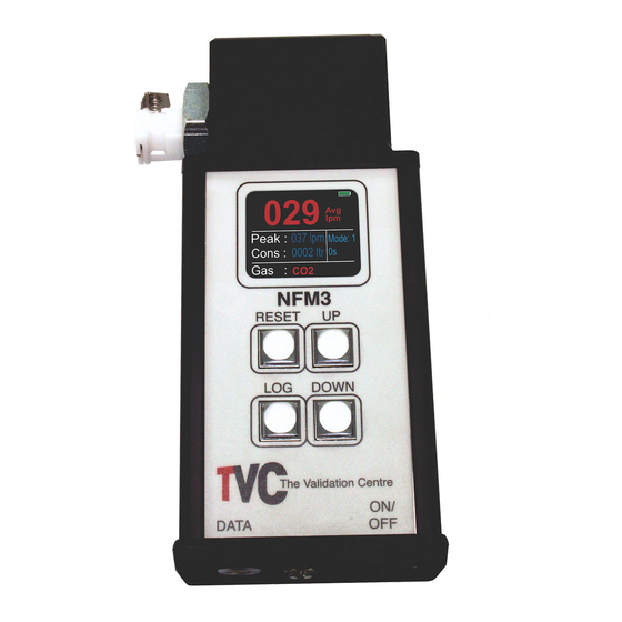
Page 4: Buttons And Connectors
1. Quick-release connector flow inlet 2. Display 3. ‘Reset’ button for resetting peak gas flow value 4. ‘Print’ button (for use with TVC weld monitors) 5. ‘Up’ button for gas type selection 6. ‘Down’ button for gas type selection 7. Input and USB/TVC weld monitor output connector 8. -
Page 5: Operation
Switch the power switch (Item 7, Section 1.2) to the ‘On’ position. The NFM3 LCD will illuminate and the software version number together with the model type will be displayed for a few seconds the screen will then revert to the standard display layout. -
Page 6: Gas Selection
Argon/Helium mixes 70 – 100% Ar-He 100% The NFM3 has a ‘button-lock’ feature to prevent accidental button presses which may change the gas selection. To access the gas selection area, press and hold the ‘Up’ button for 3 seconds. Once the buttons are unlocked and functioning, use the ‘Up’ and ‘Down’ buttons (Items 3 & 4, Section 1.2) to scroll between the available selections. -
Page 7: Flow Measurement
Flow measurement Select the required size nozzle (Items 4, 5 & 6, Section 1.1) and connect it to the NFM3 quick- release fitting. If required, use the extension hose (Item 7, Section 1.1). Insert the arc welding torch nozzle into the NFM3 nozzle, ensuring a good fit. Make sure the NFM3 is unit switched ‘On’... -
Page 8: Peak Reset
2.7.1 Mode 1 1. Switch ‘On’ the NFM3 Advanced unit. 2. By default, the NFM3 is already in ‘Mode 1’. This provides a quick screen print of the results. 3. Once the gas flow has been read, the screen will display the average gas flow, peak flow and gas consumed. - Page 9 3. Press ‘Reset’ to return to the main screen. The unit will now be in ‘Mode 2’. 4. Press the ‘Print’ button to set the NFM3 ready to record. A green bar will appear at the top of the screen to show the unit is ready to log.
- Page 10 7. After reading the gas flow for the desired time, the screen will display the average gas flow, peak and gas consumption. 8. To view the recorded data on a laptop or PC, connect the NFM3 using the USB cable provided. View using the software included with the unit (see Section 2.8 for further details).
-
Page 11: Viewing Logged Files On Nfm3 (Advanced Unit Only)
Viewing logged files on NFM3 (Advanced unit only) When the NFM3 is connected to a laptop or PC, it will appear as a removable drive in the MS- Windows ‘My Computer’ page. Open the drive by double-clicking on it and find the ‘NFM’ files. - Page 12 Once opened, click the ‘Load’ button to open a Windows file browser. Go to the NFM3 drive and select one of the logged .TXT files. Click the ‘Open’ button. The template will now open the NFM3 file and display the gas data it has found.
-
Page 13: Quick-Start Operational Flow Charts
Quick-start operational flow charts 2.9.1 Flow Chart 1: NFM3 Standard Page 12 of 15... - Page 14 2.9.2 Flow Chart 2: NFM3 Advanced – Mode 1 Page 13 of 15...
- Page 15 2.9.3 Flow Chart 3: NFM3 Advanced - Mode 2 Page 14 of 15...
-
Page 16: Battery Charging
Insert the battery charger plug into the charging input socket (Item 8; Section 1.2). Connect the battery charger to a suitable mains supply. The NFM3 battery will take between 1.5 to 2 hours to fully recharge. The unit should be disconnected from the battery charger once fully charged.
Need help?
Do you have a question about the NFM3 and is the answer not in the manual?
Questions and answers