
Related Manuals for Finerfilters RO50-NP34


Summary of Contents for Finerfilters RO50-NP34
- Page 1 01704 807600 www.finerfilters.co.uk enquiries@finerfilters.co.uk Domestic Reverse Osmosis System Installation and Maintenance Manual For Systems: RO50-NP34, RO50-NP35, RO50-NP36 RO50-A1 & RO50-A1M...
-
Page 2: Table Of Contents
Contents 1) General Information Page 2 2) System Layout and Components Page 4 3) Preparation Page 6 4) Installation Page 8 5) Maintenance Page 13 6) Filter Replacements Page 14 7) Troubleshooting Page 16... -
Page 3: General Information
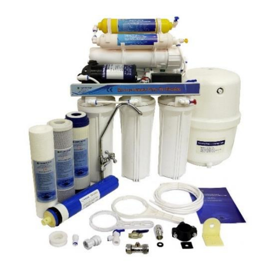
General Information O BE INSTALLED ON COLD WATER SUPPLY ONLY URN OFF MAINS WATER SUPPLY BEFORE STARTING INSTALLATION LEASE CAREFULLY READ THROUGH MANUAL BEFORE INSTALLING SYSTEM LEASE KEEP THIS MANUAL IN A SAFE PLACE NSTRUCTIONS ARE INCLUDED FOR FILTER CHANGES LEASE NOTE THAT SYSTEMS REQUIRE A MINIMUM OF PRESSURE TO WORK... - Page 4 6 Stage Unit - Stage one: Polypropylene pre-filter to remove sediment and dirt down to 5 microns. Stage two: Granular activated carbon (GAC) filter. Stage three: High density 5 Micron carbon block filter to remove chlorine. Stage four: Reverse osmosis membrane, filters down to 0.0001 micron. Stage five: Post carbon in-line filter to improve taste and odour.
-
Page 5: System Layout And Components
System Layout and Components (6 Stage Unit RO50-NP34, RO50-NP35, RO50-NP36 Three way feed water connector Ball valve C. Filter housing (PP sediment D. Filter housing (GAC cartridge) cartridge) Filter housing (carbon block Four way valve cartridge) G. RO membrane H. Membrane housing... - Page 6 System Layout and Components (6 Stage Pumped Unit RO50-A1, RO50-A1M Three way feed water connector Ball valve C. Filter housing (PP sediment D. Low pressure switch cartridge) Filter housing (GAC cartridge) Filter housing (carbon block cartridge) G. Flow in valve H.
-
Page 7: Preparation
Preparation Recommended Equipment List • Variable speed drill • Drill bit: ⅛” (for guidance) ¼” (to drain) and ½” (for tap) • Pliers • Phillips screwdriver • Plastic tube cutter / Stanley Blade The 5 metres of tubing provided is to be used at points marked 1, 2, 3 and 4 on PIC1 (page 4 &... - Page 8 Tap can be installed either attached to a wall (Fig.1) or on a counter- top (Fig. 2) Fitting types: The two types of fitting used in this installation are Quick-connect (push-fit) and JACO fitting. 1. Quick-Connect (QC) fitting: How to connect – See Fig. 3. Remove collet clip, insert tubing into fitting until it locks.
-
Page 9: Installation
Installation O BE INSTALLED ON COLD WATER SUPPLY ONLY URN OFF MAINS WATER SUPPLY BEFORE STARTING INSTALLATION HEN CUTTING TUBING TO SIZE ENSURE THAT IT IS CUT STRAIGHT WITH NO JAGGED EDGES Install tap 1. Determine location for tap, cut tubing to length (see fig.1 and 2) and install tap using the diagram below or using white fitting provided: Diagram for illustration purposes only, your tap may differ, but installation is identical. - Page 10 Connect to cold water supply 2. Cut into existing 15mm copper pipe. Screw the isolator tap into the body. Add the 15mm compression ball-o-fix fitting, take the nut and olive off the other end and screw on the isolator body. 3.
- Page 11 Assemble Main RO system 8. Remove all packaging and plastic wrapping/seals from filters. Do not include the membrane in this step. 9. Connect housings to RO system shown in PIC1 & PIC2 by hand and then use spanner provided to completely tighten. From right to left (closest to inlet): •...
- Page 12 1st System Flush- The pre-filters now need to be flushed BEFORE the membrane is added to the unit. Turn the valve on the storage tank to ‘off’. Turn on mains water supply by putting the ball-o-fix and isolator tap to ‘on’...
- Page 13 2nd System Flush- Still leaving the tank valve closed, turn the L1 valve (see PIC1 and PIC2) to the open position. Turn on the water by putting the isolator tap to ‘on’ position (1/4” turn from off position). Open the faucet and let the water run for approximately 5 minutes. Check around the unit for any leaks.
-
Page 14: Maintenance
Maintenance It is highly recommended to change your filters periodically to maintain the highest level of filtration from your RO system. Changing your filters regularly can also prolong the life of your RO system. The table (adjacent page) shows how often it is recommended to replace each filter/stage in your system. -
Page 15: Filter Replacements
Replacement Filter Codes: Please enter these codes into the search bar on our website: System Code Filter Codes WITHOUT Filter Codes WITH Membrane Membrane RO50-NP34 FF-RO-REPL-D4 FF-RO-REPL-D4-50GPD RO50-NP35 & FF-RO-REPL-D5 FF-RO-REPL-D5-50GPD RO50-A1 RO50-NP36 & FF-RO-REPL-D6 FF-RO-REPL-D6-50GPD RO50-A1M All replacement filters and membranes can be purchased through our website www.finerfilters.co.uk... - Page 16 Post In-Line filter(s) including Mineral Filter - Inline Post Filter(s) - Remove the collet clips from the fitting and using the quick release, remove the tubing on both sides. (Lift filter off bracket if easier). Un-screw the fittings from the end of the inline filter. Dispose of exhausted filter.
-
Page 17: Troubleshooting
Troubleshooting Symptom Probable Cause Solution 1.Water supply is off 1. Turn water supply on and/or isolator tap in on position 2.Tank valve is in ‘off’ 2. Turn Valve to ‘on’ position No water from tap position 3.Tank improperly 3. Set tank pressure to 5- pressurised 7psi when empty 4.Pre, or post filter... - Page 18 1. Membrane not 1. Check membrane is installed correctly installed as instructed 2. If TDS reading is below 2. Bad membrane 80%, replace Bad taste or odour Membrane 3. New system (or new 3. Ensure the correct filters/membrane) flushing instructions are followed and the tank is allowed to fill once and expelled before water is...
Need help?
Do you have a question about the RO50-NP34 and is the answer not in the manual?
Questions and answers