
Related Manuals for Finerfilters RO-H-50G


Summary of Contents for Finerfilters RO-H-50G
- Page 1 01704 807600 www.finerfilters.co.uk enquiries@finerfilters.co.uk Compact Reverse Osmosis System Installation and Maintenance Manual For Systems - RO-H-50G, RO-H-75G, RO-H-100G, RO-H1-50G, RO-H1-75G, RO-H1-100G...
-
Page 2: Table Of Contents
Contents 1) General Information Page 2 2) System Layout and Components Page 3 3) Preparation Page 4 4) Installation Page 6 5) Maintenance Page 10 6) Replacement Filters Page 11 7) Troubleshooting Page 12... -
Page 3: General Information
General Information O BE INSTALLED ON COLD WATER SUPPLY ONLY URN OFF MAINS WATER SUPPLY BEFORE STARTING INSTALLATION LEASE CAREFULLY READ THROUGH MANUAL BEFORE INSTALLING SYSTEM LEASE KEEP THIS MANUAL IN A SAFE PLACE NSTRUCTIONS ARE INCLUDED FOR FILTER CHANGES LEASE NOTE THAT SYSTEMS REQUIRE A MINIMUM OF PRESSURE TO WORK... - Page 4 3 Stage Unit - Stage one: Polypropylene pre-filter to remove sediment and dirt down to 5 microns. Stage two: Granular activated carbon (GAC) filter to remove chlorine. Stage three: Reverse osmosis membrane, filters down to 0.0001 micron. 4 Stage Unit – Post DI resin filter chamber (Refillable) to remove the remaining ions.
-
Page 5: System Layout And Components
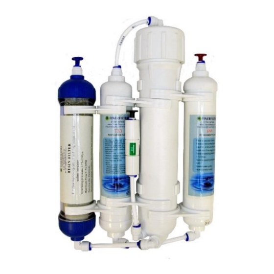
System Layout and Components RO-H-50G, RO-H-75G, RO-H-100G, RO-H1-50G, RO-H1-75G, RO- H1-100G A. Three way valve B. Ball valve C. PP sediment filter cartridge D. Carbon inline filter cartridge E. RO membrane housing F. RO membrane G. Flow restrictor 4 Stage Unit – Includes a post membrane DI Resin Filter Chamber (Refillable). -
Page 6: Preparation
Preparation Recommended Equipment List • Variable speed drill • Drill bit: ⅛” (for guidance) ¼” (to drain) and ½” (for tap) • Pliers • Phillips screwdriver • Plastic tube cutter / Stanley Blade The 5 metres of tubing provided is to be used at the points marked by the coloured stoppers on the RO system. - Page 7 Fitting type: 1. Quick-Connect (QC) fitting: How to connect – See Fig. 3. Remove collet clip, insert tubing into fitting until it locks. Gently pull tubing back to ensure fit is secure. Re-place collet clip. How to disconnect – See Fig. 4. Remove collet clip, push down on collet so it is completely flush with the fitting and pull tubing simultaneously.
-
Page 8: Installation
Installation O BE INSTALLED ON COLD WATER SUPPLY ONLY URN OFF MAINS WATER SUPPLY BEFORE STARTING INSTALLATION HEN CUTTING TUBING TO SIZE ENSURE THAT IT IS CUT STRAIGHT WITH NO JAGGED EDGES Connect to cold water supply 1. Cut into existing 15mm copper pipe. Screw the isolator tap into the body. - Page 9 4. Taking the side of the drain clamp with the QC fitting, stick the self- adhesive sponge provided to the inside of the drain clamp (remove centre piece of sponge beforehand). Place one half of the plastic clamp on either side of the drain pipe with, and clamp loosely using the nuts and bolts included.
- Page 10 1st System Flush- The pre-filters now need to be flushed BEFORE the membrane is added to the unit. Turn on mains water supply by putting the ball-o-fix and isolator tap to ‘on’ position (1/4” turn from off position). (The ball-o-fix fitting can be left in ‘on’...
- Page 11 (Final) System Flush – Turn on the water by putting the isolator tap to ‘on’ position (1/4” turn from off position). You will hear the RO unit starting to produce water. Double check the unit for leaks. (As per 1 system flush).
-
Page 12: Maintenance
RO-H 50G FF-RO-REPL-COMP-3 FF-RO-REPL-COMP-3-75GPD RO-H 75G FF-RO-REPL-COMP-3 FF-RO-REPL-COMP-3-100GPD RO-H 100G FF-RO-REPL-COMP-3 FF-RO-REPL-COMP-4-50GPD RO-H1 50G FF-RO-REPL-COMP-4 FF-RO-REPL-COMP-4-75GPD RO-H1 75G FF-RO-REPL-COMP-4 FF-RO-REPL-COMP-4-100GPD RO-H1 100G FF-RO-REPL-COMP-4 All replacement filters and membranes can be purchased through our website www.finerfilters.co.uk or call us on 01704 807600. -
Page 13: Replacement Filters
Replacing your filters- (Filters only, not membrane)- Please have some towels and cloths ready as some water will escape from the unit. Turn off the water by putting the isolator tap to ‘off’ position (1/4” turn from on position). Drain as much water from the unit as possible. *REMOVE THE MEMBRANE FROM THE HOUSING AND SET ASIDE UNTIL FILTERS HAVE BEEN CHANGED AND THE UNIT FLUSHED*... -
Page 14: Troubleshooting
Troubleshooting Symptom Probable Cause Solution 1. Water supply is off 1. Turn water supply on and/or isolator tap in on position 2. Fault on non-return valve 2. Fitting requires replacing No water 3.Pre, or post filter clogged 3. Check/replace pre, or post filter 4. - Page 15 Leaking membrane 2. Check for any leaks in housing membrane housing or cap. Replace if cracked. 3. O-ring not seated properly 3. Make sure O-ring is in groove and lubricated (Membrane housing see insert membrane on pg 1. Defective 1. Replace if TDS reading membrane is below 85% Cloudy/milky water...
Need help?
Do you have a question about the RO-H-50G and is the answer not in the manual?
Questions and answers