
Related Manuals for AxFlow SVM Series


Summary of Contents for AxFlow SVM Series
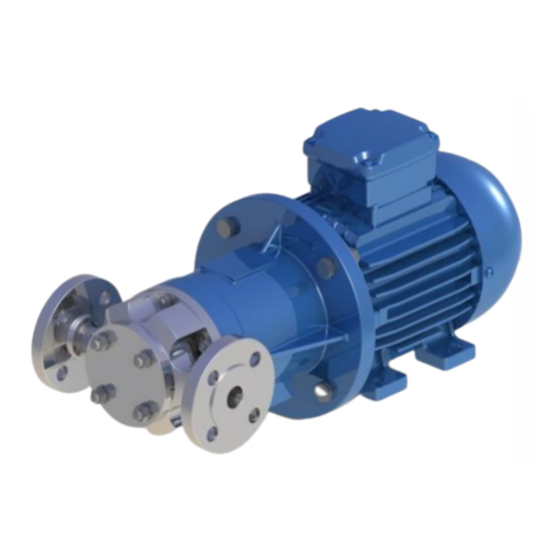
- Page 1 SVM SERIES OPERATION & MAINTENANCE MANUAL Seal Less Magnetically Coupled Sliding Vane Pump...
- Page 2 Installation and operation should be carried out by qualified personnel only. Danger of electrocution. Electric supply must be isolated before working on the pumpset. Electrical work should only be carried out by qualified personnel Page i SVM Series Operating & Instruction Manual...
- Page 3 Keep the inlet pipe as short and straight as possible. If self-priming is required, ensure that the inlet line is completely airtight. The bore of the inlet and discharge pipes should be at least as large as the nominal bore of the pump ports. Page ii SVM Series Operating & Instruction Manual...
- Page 4 (a fuse protects only the wiring); withstand the heavy starting current of the motor, preventing arcing and rapid contact wear. Page iii SVM Series Operating & Instruction Manual...
-
Page 5: Table Of Contents
Pump operation ..........................20 MAINTENANCE ............................. 22 Supply isolation ..........................22 Maintenance schedule ........................22 DISASSEMBLY ............................23 Strong magnet essential precautions ....................23 Decommissioning the pump ......................24 Disassembling the pump ........................24 Page iv SVM Series Operating & Instruction Manual... - Page 6 Refitting the external magnet (with its bearing housing or motor) to the pump ......33 Refitting the coupling (long-coupled units only) ................33 Typical cross-section ..........................34 SVM 1 ..............................34 SVM 1.5 .............................. 36 SVM 2 ..............................38 Troubleshooting............................. 40 Notes ..............................46 Page v SVM Series Operating & Instruction Manual...
-
Page 7: General
field at 1 meter from the pump set and elaborated according to ISO standard R1680 – curve A). The values are referred to groups with AxFlow standard electric motors. For other motors the table values shall be compared to the actual used motors. -
Page 8: Area Of Operation
GENERAL Area of operation AxFlow Aturia SVM pump sets may be installed within a building or externally. Wherever installed, protect the pump from frost, snow and flooding. Care must be taken to ensure that cold weather will not cause the pump or pipes to freeze, and installers may wish to consider lagging or trace heating. -
Page 9: Transport
If the reading is below 10 Mega ohms, move to a warm dry place for a few hours until the motor insulation value rises. Do not remove flange covers until the pump is ready to be connected to the pipework. Page 3 SVM Series Operating & Instruction Manual... -
Page 10: Drivers
GENERAL Drivers AxFlow Aturia SVM pumps may be driven by an electric motor through a shaft -to-shaft coupling. There are particular points which can affect the pump: · Shaft -to-shaft flexible couplings must be properly aligned, as poor alignment will cause high loads on the pump bearings. -
Page 11: Installation
firmly and evenly on its foundation: it must not be distorted by bolting to an uneven surface, which will throw the pump and motor out of alignment. Page 5 SVM Series Operating & Instruction Manual... -
Page 12: Pump And Motor Alignment
The flexible coupling is not designed to compensate for misalignment. Improper alignment will cause vibration and premature bearing failure. CHECK THE ALIGNMENT OF PUMP AND MOTOR PRIOR TO START -UP Page 6 SVM Series Operating & Instruction Manual... -
Page 13: Methods Of Checking Alignment
It relies for its accuracy on the accurate alignment of each coupling half on its shaft. The straight edge method is a useful preliminary check, but should not be seen as an effective final alignment method. Page 7 SVM Series Operating & Instruction Manual... -
Page 14: Dial Gauge ("Clocking")
Optical methods Several proprietary systems are available, such as the `OPTALIGN' system (INA Linear Systems). Mechanical errors are eliminated by optical alignment techniques. On request, AxFlow can provide further information about suitable alignment methods, including allowances for THERMAL EXPANSION IN HIGH TEMPERATURE USE . - Page 15 The discharge line should be as short and direct as possible to minimize friction losses. An air vent (if permissible) should be installed at the first high point in the discharge line. Page 9 SVM Series Operating & Instruction Manual...
- Page 16 CONTAINING SUSPENDED SOLIDS Standard AxFlow pumps are designed to handle clean liquids. Unless specifically agreed prior to purchase of the pump from your supplier, suspended solid matter must be kept out of the pump by a suitable inlet strainer. The strainer mesh size should be less than 0.5mm, with an open surface area at least 2.5 x nominal cross-sectional area of pump inlet bore.
-
Page 17: Admissible External Forces And Torques On Pump Flanges
INSTALLATION Admissible external forces and torques on pump flanges TORQUES, (daN) MOMENTS, (daN.m) TYPE FLANGE ΣF ΣM Suction 1x… Delivery Suction 1.5x… Delivery Suction 2x… Delivery Page 11 SVM Series Operating & Instruction Manual... -
Page 18: Protecting The Pump Against Dry Running
It is easily fitted in the power supply to the motor, in place of a normal starter. Details of power monitors are available on request from your pump supplier. Page 12 SVM Series Operating & Instruction Manual... -
Page 19: Electrical Connection
Page 13 SVM Series Operating & Instruction Manual... -
Page 20: Check Direction Of Rotation
flows out of the bulb. If there is a toothed spacer coupling between the pump and the motor, check whether it needs to be filled with oil. Follow the coupling manufacturer's instructions as required. Page 14 SVM Series Operating & Instruction Manual... -
Page 21: Direction Of Rotation
INSTALLATION Direction of rotation AxFlow Aturia SVM series pumps rotate clockwise when viewed from in front of the pump. To confirm the direction of rotation (refer to the rotational arrow on the pump casing) use the following procedure: a. Open the suction and discharge valves, allowing the pump to fill with liquid. -
Page 22: Operation
OPERATION Supervision When correctly installed and operated, this AxFlow pump will give many years of trouble free service. In operation, the pump should be free from vibration and run smoothly. Any changes to smoothness of operation should be investigated immediately. The pump should be visually checked periodically. - Page 23 IMPORTANT: do not run the pump in reverse. Reverse rotation will lead to accelerated wear and eventual failure. The direction of flow may be reversed simply by rotating the pump and adaptor through 180° on the motor flange. Page 17 SVM Series Operating & Instruction Manual...
- Page 24 To alter the direction of rotation of a three-phase motor changes any two connections. For a single-phase motor, reverse the polarity of the start winding in relation to the main winding. IF IN DOUBT OR DIFFICULTY, OBTAIN THE ASSISTENCE OF A QUALIFIED ELECTRICIAN Page 18 SVM Series Operating & Instruction Manual...
-
Page 25: Priming The Pump
If the flow rate needs to be permanently restricted, a permanent orifice in the discharge line is more secure than an adjustable valve. Your pump supplier will advise on a suitable orifice size if necessary. Page 19 SVM Series Operating & Instruction Manual... -
Page 26: Pump Operation
Do not allow the pump to run against a closed discharge valve for more than a few seconds. This will cause rapid heating of the liquid in the pump casing, with vaporization and dry running of the bearings, risking serious damage to the pump. Page 20 SVM Series Operating & Instruction Manual... - Page 27 Do not start the pump while it is turning backwards, as this can result in immediate and severe damage. Allow ample time for complete drainage of the discharge line before the pump is restarted. Page 21 SVM Series Operating & Instruction Manual...
-
Page 28: Maintenance
Provided the pumped liquid is clean and free of suspended solids, and the pump is operated within the manufacturer's stated performance limits and is not allowed to run dry, your AxFlow Aturia pump is capable of running for very long periods with minimal attention. Please see previous PUMP OPERATION section. -
Page 29: Disassembly
IF MAGNETIC PARTICLES GET INTO THE EYES, GET MEDICAL HELP IMMEDIATELY! HEART PACEMAKERS CAN BE DAMAGED! TOOLS OR OTHER IRON OBJECTS CAN BE ATTRACTED SUDDENLY! CARDS WITH MAGNETICALLY STORED INFORMATION, I.E. CREDIT CARDS, ETC., CAN BE DAMAGED! WATCHES CAN BE DAMAGED! Page 23 SVM Series Operating & Instruction Manual... -
Page 30: Decommissioning The Pump
LABELLED, stating what substances or residues it may contain, warning the recipient of any possible hazard to health. Page 24 SVM Series Operating & Instruction Manual... -
Page 31: Disassembling The Pump
1. Check that the pump has been fully drained and flushed out, before you start work on it. 2. Isolate the motor from its electrical supply. 3. Isolate the pump from the rest of the hydraulic system. Isolate and disconnect any jacketing or other auxiliary pipework from the pump. Page 25 SVM Series Operating & Instruction Manual... - Page 32 6. The complete pump casing can now be removed from the adaptor, together with the O-ring seal. 7. Remove the four end screws from the pump head. Remove the end cover and the front O-ring seal. Page 26 SVM Series Operating & Instruction Manual...
- Page 33 The securing pin must be tapped out, with the rotor shaft held on a suitable support. 12. Slide the magnet off the rotor shaft. The rotor and vane spacing pins ca n now be removed from the pump body, together with the rear graphite disc. Page 27 SVM Series Operating & Instruction Manual...
-
Page 34: Reassembly
To locate the disc correctly ensure that the port slots are aligned with the pump ports, with the liquid lubrication holes on the side corresponding to the discharge. HEAT WITH HOT WATER THE PUMP HEAD TO FACILITATE GRAPHITE INSERTION Page 28 SVM Series Operating & Instruction Manual... - Page 35 11. Now slide the internal magnet on the rotor shaft and secure it with the expanding shaft pin. When inserting the pin, ensure that the shaft is correctly supported. (See Disassembly Section). Page 29 SVM Series Operating & Instruction Manual...
-
Page 36: Pumping Dense And/Or Viscous Liquids
THESE VALUES ARE PURELY INDIC ATIVE. CONTACT AXFLOW TECHNICAL DEPARTMENT FOR ADVICE ON PARTICULAR APPLICATIONS Service kits are available for all AxFlow Aturia SVM-series sliding vane pumps, containing the complete internal rotating and static assembly together with static seal and gasket. -
Page 37: Replacing The External Magnet And Motor Or Bearing Housing
See table below for correct positioning of the magnet on the shaft. DO NOT STRIKE THE MAGNET! The magnet elements are brittle and are easily damaged. Page 31 SVM Series Operating & Instruction Manual... - Page 38 Fill the bearing housing with oil to the middle of the sight glass. FOR LONG COUPLED PUMPS ONLY: Fill the bearing housing with oil to the middle of the sig h t-glass. Page 32 SVM Series Operating & Instruction Manual...
-
Page 39: Refitting The External Magnet (With Its Bearing Housing Or Motor) To The Pump
Fit the two coupling halves to their shafts, checking that they run concentrically. Fit the spacer (if present). Check the coupling carefully for correct ALIGNMENT (see METHODS OF CHECKING ALIGNMENT instr u ctions). Page 33 SVM Series Operating & Instruction Manual... -
Page 40: Typical Cross-Section
TYPICAL CROSS-SECTION YPICAL CROSS SECTION SVM 1 Page 34 SVM Series Operating & Instruction Manual... - Page 41 Rear Casing Labyrinth Seal Ring Screw Bracket Shaft External Magnet Rotor Shaft Bearing Cover Rub Ring Constant Level Oil Screw Drain Plug O-Ring Screw / Washer Pedestal Guide Pin Screw / Washer Bearing Page 35 SVM Series Operating & Instruction Manual...
-
Page 42: Svm 1.5
TYPICAL CROSS-SECTION SVM 1.5 Page 36 SVM Series Operating & Instruction Manual... - Page 43 Rear Ball Bearing Screw Labyrinth Seal Ring External Magnet Bracket Shaft Rotor Shaft Bearing Cover Rub Ring Constant Level Oil Screw Drain Plug O-Ring Screw / Washer Pedestal Guide Pin Screw / Washer Page 37 SVM Series Operating & Instruction Manual...
-
Page 44: Svm 2
TYPICAL CROSS-SECTION SVM 2 Page 38 SVM Series Operating & Instruction Manual... - Page 45 Rear Casing Gasket Screw Rear Ball Bearing External Magnet Labyrinth Seal Ring Rotor Shaft Bracket Shaft Rub Ring Bearing Cover Screw Constant Level Oil O-Ring Drain Plug Adaptor Flange with Thermocouple Connection Page 39 SVM Series Operating & Instruction Manual...
-
Page 46: Troubleshooting
Regular inspection, and preventive maintenance when necessary, will help to prevent breakdowns. There are many possible reasons why a pump may not run properly. If your AxFlow Aturia SVM-Series pump does not run satisfactorily, be prepared to look critically at the system as well as at the pump itself. - Page 47 Liquid contains entrained air or · Fit baffles in supply tank to prevent vortexing. vapour · Fit a settling tank in the inlet line to allow entrained gas to separate from the liquid. Page 41 SVM Series Operating & Instruction Manual...
- Page 48 · Use a soft start system for pump starting. Insufficient depth of immersion of · Increase the depth of immersion of the the suction pipe end under the suction pipe level of the liquid Page 42 SVM Series Operating & Instruction Manual...
- Page 49 Undersized motor supplier. Incorrectly set motor overload cut Check motor overload setting · Electronic dry running protector · Check for loss of flow. has tripped · Check for loss of liquid supply. Page 43 SVM Series Operating & Instruction Manual...
- Page 50 · Check pipework alignment and support. Refer pipework to LOCATION AND PIPING section. Pump starting while rotating in · Stop pump immediately and allow discharge reverse line to drain completely before re-starting. Page 44 SVM Series Operating & Instruction Manual...
- Page 51 · Drain and replace oil if necessary. Incorrect oil in bearing housing · Replace bearings if necessary. Excessive temperature of · Refill bearing housing with correct oil for pumped liquid working temperature of the pump. Page 45 SVM Series Operating & Instruction Manual...
-
Page 52: Notes
NOTES OTES Page 46 SVM Series Operating & Instruction Manual... - Page 53 Newton Aycliffe County Durham DL5 6ZF Tel: 01325 327322 Email: neservice@axflow.co.uk Windsor Office Unit 5 Millside Park Crouch Lane Winkfield Windsor Berkshire SL4 4PX Tel: 01344 886633 Email: soservice@axflow.co.uk Web Site: www.axflow.co.uk Page 47 SVM Series Operating & Instruction Manual...
Need help?
Do you have a question about the SVM Series and is the answer not in the manual?
Questions and answers