
Related Manuals for AxFlow Aturia NA Series


Summary of Contents for AxFlow Aturia NA Series
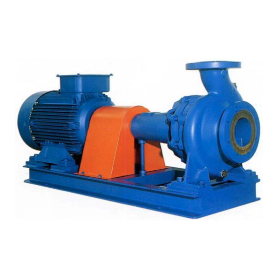
- Page 1 NA SERIES OPERATION & MAINTENANCE MANUAL Single Stage Mechanically Coupled End Suction Centrifugal Pump built to DIN 25255 standard...
- Page 2 IMPORTANT NOTES Read these instructions before putting the pump into service. Installation and operation should be carried out by qualified personnel only. Danger of electrocution. Electric supply must be isolated before working on the pumpset. Electrical work should only be carried out by qualified personnel Page i NA Series Operating &...
-
Page 3: Table Of Contents
CONTENTS GENERAL ..............................1 Precautions during operation ....................... 1 Noise levels ............................1 Operating limits ........................... 2 Residual risks ............................3 In case of emergency ..........................3 Area of operation ..........................4 Spare parts ............................4 Transport ............................. 5 Storage ..............................6 Storage for a period shorter than 3 months ..................6 Storage for a period exceeding 3 months (but shorter than 12 months) ...........6 Storage (after operation) ........................6 Drivers .............................. - Page 4 CONTENTS MAINTENANCE ............................. 22 Supply isolation ..........................22 Maintenance schedule ........................22 Gland packing ............................ 23 Mechanical seal ..........................23 Bearings ............................. 23 Grease lubricated ........................... 23 Oil lubricated ..........................24 Oil type............................... 24 Pump stop for long period ........................24 DISASSEMBLY ............................
-
Page 5: General
GENERAL GENERAL AxFlow Aturia NA series pumps are single stage mechanically coupled end suction pumps. Details of the pump type and model, serial number and operating data are indicated on the pump nameplate. The pump must be installed and operated in full compliance with these instructions. The pump may not be operated outside the limits specified on the nameplate and within this manual. -
Page 6: Noise Levels
GENERAL Noise levels The following table reports the noise level produced by AxFlow Aturia NA series pumps running with in their operating limits and installed according to the instructions given in this manual (average values measured in free field at 1 meter from the pump set and elaborated according to ISO standard R1680 –... -
Page 7: Residual Risks
GENERAL Residual risks Inobservance of the safety instructions here reported or improper use of the pump may result in heavy damage to things and/or injuries to the person. Always keep to the following directions : DON’T KICK THE PUMP DON’T DAMAGE THE PUMP BY MISHANDLING DON’T PRESSURIZE THE PUMP BEYOND... -
Page 8: Area Of Operation
GENERAL Area of operation AxFlow Aturia NA series pump sets may be installed within a building or externally. Wherever installed, protect the pump from frost, snow and flooding. Care must be taken to ensure that cold weather will not cause the pump or pipes to freeze, and installers may wish to consider lagging or trace heating. -
Page 9: Transport
GENERAL Transport Check the nameplate on the pump against the receiving and purchase order documents to be sure that the correct size of pump and materials of construction have been supplied. If a motor has been supplied, check that the power, speed, and voltage are correct. Prior to unpacking, check for physical damage to the packing and the pump unit and notify the forwarding agent IMMEDIATELY if any damage is found. -
Page 10: Storage
GENERAL Storage The delivered pump is generally suitable for immediate installation. Storage for a period shorter than 3 months Store the pump in a dry and sheltered area. Check that ambient temperature never falls below 5°C. It is recommended that the pump shaft is rotated at regular intervals ( every 30 days ): this prevents damage to the bearings and seizure of the rotating parts. -
Page 11: Drivers
GENERAL Drivers AxFlow Aturia NA series pumps may be driven by an electric motor through a shaft -to-shaft coupling. There are particular points which can affect the pump: Shaft -to-shaft flexible couplings must be properly aligned, as poor alignment will cause high loads on the pump bearings. -
Page 12: Installation
INSTALLATION INSTALLATION Isolate the supply before commencing work on the pump. Foundations The foundation should be substantial in order to reduce vibrations, and rigid enough to prevent flexing which can result in misalignment. Foundation bolts of the correct size should be located by reference to certified drawings if the baseplate is supplied with the pump. -
Page 13: Pump And Motor Alignment
INSTALLATION Pump and motor alignment Long-coupled pumps have been pre-aligned with the motor prior to shipment. If pump units receive rough treatment during shipment, they can become misaligned. The flexible coupling is not designed to compensate for misalignment. Improper alignment will cause vibration and premature bearing failure. -
Page 14: Methods Of Checking Alignment
INSTALLATION A final alignment check should be made after the baseplate has been grouted and set, and the foundation bolts have been tightened. TYPE DISPLACEMENT Short flexible coupling 0.04 mm per 100 mm 0.05 mm (3000 rpm) coupling diameter Flexible spacer coupling 0.07 mm per 0.04 mm per 100 mm (3000 rpm) -
Page 15: Dial Gauge ("Clocking")
Optical methods Several proprietary systems are available, such as the `OPTALIGN' system (INA Linear Systems). Mechanical errors are eliminated by optical alignment techniques. On request, AxFlow can provide further information about suitable alignment methods, including allowances for THERMAL EXPANSION IN HIGH TEMPERATURE USE. - Page 16 INSTALLATION ATTENTION ! Valves on the suction side should be mounted with stems horizontal, or vertically downwards. All joints in the suction line must be tight, to prevent air from entering into the system, with the risk of vapour locking. If the pump is installed with a negative static inlet head (lower diagram), the foot valve/ strainer must always be immersed at a sufficient depth to avoid entry of air into the pump.
- Page 17 CONTAINING SUSPENDED SOLIDS Standard AxFlow pumps are designed to handle clean liquids. Unless specifically agreed prior to purchase of the pump from your supplier, suspended solid matter must be kept out of the pump by a suitable inlet strainer. The strainer mesh size should be less than 0.5mm, with an open surface area at least 2.5 x nominal cross-sectional area of pump inlet bore.
-
Page 18: Admissible External Forces And Torques On Pump Flanges
INSTALLATION Admissible external forces and torques on pump flanges TORQUES, (daN) MOMENTS, (daN.m) TYPE FLANGE ΣF ΣM 3x12 Suction 3x16 3x20 Delivery 3x25 4x12 Suction 4x16 4x20 4x25 Delivery 4x31 5x12 Suction 5x16 5x20 5x25 Delivery 5x31 6x12 Suction 6x16 6x20 6x25 Delivery... -
Page 19: Protecting The Pump Against Dry Running
INSTALLATION Protecting the pump against dry running The pump must not be allowed to run dry. Dry running will result in loss of liquid film to the bearings, causing over-heating and eventual bearing failure, leading to seizure of the pump. Avoid the following conditions: Loss of liquid supply Ensure that an adequate supply of liquid is available at the pump inlet at all times. -
Page 20: Electrical Connection
INSTALLATION Isolate the supply before commencing work on the pump Electrical connection The electrical connection to the motor should be carried out by a properly qualified electrician, using cable, cable glands and connection procedures suitable for the electrical load and for the location of the installation. -
Page 21: Oil Lubricated
INSTALLATION Oil lubricated Bearings It is very important to check the bearing operation, their temperature and the oil level. Check bearing housing temperature: it can raise up to 50°C above the ambient temperature, but it should never exceed 90°C. For the first start-up it is recommended to replace the oil after 50 hours running. ... -
Page 22: Direction Of Rotation
INSTALLATION Direction of rotation AxFlow Aturia NA series pumps rotate anti-clockwise when viewed from in front of the pump inlet nozzle. To confirm the direction of rotation (refer to the rotational arrow on the pump casing) use the following procedure: a. -
Page 23: Operation
OPERATION Supervision When correctly installed and operated, this AxFlow pump will give many years of trouble free service. In operation, the pump should be free from vibration and run smoothly. Any changes to smoothness of operation should be investigated immediately. -
Page 24: Start-Up
OPERATION Start-up Before starting the pump : Check motor direction of rotation ( when the pump is disconnected ); if the motor rotates in the wrong direction, reverse two electric cables and change the position in the terminal box. ... - Page 25 OPERATION AxFlow Aturia pumps are dynamically balanced during manufacture and are tested prior to dispatch to ensure that they run smoothly and without vibration. Replacement impellers are also balanced prior to dispatch. Vibration monitoring in service can detect poor hydraulic conditions, bearing wear, internal erosion or chemical attack before it seriously damages the pump.
-
Page 26: Maintenance
Provided the pumped liquid is clean and free of suspended solids, and the pump is operated within the manufacturer's stated performance limits and is not allowed to run dry, your AxFlow Aturia pump is capable of running for very long periods with minimal attention. Please see previous PUMP OPERATION section. -
Page 27: Gland Packing
MAINTENANCE Gland packing The lack of lubrication could cause packing and shaft sleeve overheating with the possible consequence of seizing. Replace the packing when necessary, considering that the material dimension and quality have to be suitable to the service. Replace all seal rings and not only the last external rings. Removing the worn rings, check stuffing box sleeve condition: if it is rough and has evidence of wear marks, it is advisable to replace this item. -
Page 28: Oil Lubricated
MAINTENANCE Oil lubricated It is very important to check the bearing operation, their temperature and the oil level. Check bearing housing temperature: it can raise up to 50°C above the ambient temperature, but it should never exceed 90°C. For the first start-up it is recommended to replace the oil after 50 hours running. ... -
Page 29: Disassembly
REASSEMBLY DISASSEMBLY Disassembling the pump These operations should be carried out only by skilled personnel. Damage caused by careless or improper disassembly or reassembly is excluded from the supplier's guarantee. WORK IN A CLEAN AREA! ISOLATE PUMP MOTOR BEFORE DISASSEMBLY! DO NOT USE FORCE! The pump should be taken apart with the help of the labelled sectional drawing(s) supplied with it. -
Page 30: Support And Rotor Disassembling
REASSEMBLY Support and rotor disassembling 1. Unscrew the impeller nut 2. Remove the impeller 3. Remove the key For lifting instructions, please refer to GENERAL Transport section . Gland packing inspection 1. Remove from the complete support the stuffing box housing with the gland collar, the packing, the shaft sleeve and the shaft sleeve gasket. -
Page 31: Reassembly
REASSEMBLY REASSEMBLY WORK IN A CLEAN AREA! Before reassembling 1. Clean all components carefully. 2. Make sure that all mounting surfaces are free from defects ( mainly those in contact with gaskets ) 3. Verify the wear ring clearance, any increase reduces pump performances. The clearances can be restored by replacing worn components. -
Page 32: Mechanical Seal Reassembling
REASSEMBLY Mechanical seal reassembling Before mechanical seal assembling, take particular care of each component and do not damage the seal parts and lapped surfaces. Pump with integral mechanical seat site in stuffing box housing : 1. insert the stationary ring, complete with gasket, in the site on the stuffing box housing, assembling it on the complete support. -
Page 33: Typical Cross-Section
TYPICAL CROSS-SECTION TYPICAL CROSS-SECTION NE 6x31 – NE 8x31 – NE 10x31 – NE 10x40 – NE 12x31 – NE 12x40 – NE 15x31 – NE 15x40 Page 29 NA Series Operating & Instruction Manual... - Page 34 TYPICAL CROSS-SECTION NE 5x31 – NE 8x40 – NE 15x25 – NE 15x50 – NE 20x31 – NE 20x40 – NE 20x50 – NE 25x31 – NE 25x40 – NE 25x50 Page 30 NA Series Operating & Instruction Manual...
- Page 35 TYPICAL CROSS-SECTION POS. POS. DESCRIPTION DESCRIPTION 1111 Pump Casing 4200** Mechanical Seal 1510** Wear Ring, suction side 4213 Mechanical Seal Cover 1520** Wear Ring, delivery side 4590** Pump Casing Gasket 2110 Pump Shaft 4590.1** Shaft Sleeve Gasket 2200** Impeller 4590.2** Plug Gasket 2450** Shaft Sleeve 4590.3** Plug Gasket...
-
Page 36: Troubleshooting
Regular inspection, and preventive maintenance when necessary, will help to prevent breakdowns. There are many possible reasons why a pump may not run properly. If your AxFlow Aturia NA Series pump does not run satisfactorily, be prepared to look critically at the system as well as at the pump itself. - Page 37 TROUBLESHOOTING PROBLEM PROBABLE CAUSE SOLUTION Increase speed of rotation if possible. Fit larger diameter impeller. Reduce total head of system. Actual total discharge head Increase discharge pipework size. exceeds rated head of pump Check that discharge valve is fully open. ...
- Page 38 TROUBLESHOOTING PROBLEM PROBABLE CAUSE SOLUTION Reduce liquid temperature. Check inlet line for air leaks. Check for loss of liquid supply. Pump has lost its prime Re-prime pump. Refer to OPERATION section. Check for blockage in the inlet pipework. ...
- Page 39 TROUBLESHOOTING PROBLEM PROBABLE CAUSE SOLUTION Decrease suction lift (negative head). Increase static suction (positive head) Low inlet pressure, with Check for inlet obstructions or cavitation, loss of efficiency and restrictions. loss of liquid film in the pump ...
- Page 40 TROUBLESHOOTING PROBLEM PROBABLE CAUSE SOLUTION Decrease suction lift (negative head). Increase static suction (positive head) Low inlet pressure, with Check for inlet obstructions or cavitation, loss of efficiency and restrictions. loss of liquid film in the pump ...
-
Page 41: Decommissioning And Dismantling
DECOMMISSIONING DECOMMISSIONING AND DISMANTLING When pump is permanently stopped and dismantled, its various components should be properly disposed of. Make sure that no residual polluting liquids are trapped with the pump. The disposal of polluting liquids and materials should follow current environment regulations. -
Page 42: Notes
NOTES NOTES Page 38 NA Series Operating & Instruction Manual... - Page 43 Newton Aycliffe County Durham DL5 6ZF Tel: 01325 327322 Email: neservice@axflow.co.uk Windsor Office Unit 5 Millside Park Crouch Lane Winkfield Windsor Berkshire SL4 4PX Tel: 01344 886633 Email: soservice@axflow.co.uk Web Site: www.axflow.co.uk Page 39 NA Series Operating & Instruction Manual...
Need help?
Do you have a question about the Aturia NA Series and is the answer not in the manual?
Questions and answers