
Related Manuals for AxFlow Aturia ND Series


Summary of Contents for AxFlow Aturia ND Series
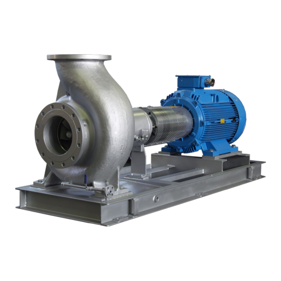
- Page 1 ND SERIES OPERATION & MAINTENANCE MANUAL Single Stage Mechanically Coupled End Suction Centrifugal Pump built to ISO 2858 – ISO 5199 standard...
- Page 2 IMPORTANT NOTES Read these instructions before putting the pump into service. Installation and operation should be carried out by qualified personnel only. Danger of electrocution. Electric supply must be isolated before working on the pumpset. Electrical work should only be carried out by qualified personnel Page i ND Series Operating &...
-
Page 3: Table Of Contents
CONTENTS GENERAL ..............................1 Construction features ........................... 1 Pump casing ............................. 1 Shaft seal housing ..........................1 Support ............................1 Pump nameplate ..........................1 Fields of applications ..........................2 Precautions during operation ....................... 3 Noise levels ............................3 Operating limits ........................... 5 Residual risks ............................ - Page 4 CONTENTS OPERATION ............................22 Supervision ............................22 Priming the pump ..........................22 Start-up .............................. 23 Pump operation ..........................24 MAINTENANCE .............................26 Supply isolation ..........................26 Maintenance schedule ........................26 Mechanical seal ..........................27 Bearings ............................. 27 Grease lubricated ........................... 27 Oil lubricated ..........................27 Oil type...............................
- Page 5 CONTENTS ATEX CLASSIFIED PUMPS ........................49 Introduction ............................49 Pump installation in classified areas ....................50 Suitability of the pump in installation area ..................50 Areas where gas, vapour or flammable clouds are present ............. 50 Plate data regarding safety ........................ 51 Supplementary plate ........................
-
Page 6: General
GENERAL GENERAL Construction features AxFlow Aturia ND series pumps are single stage pumps with hydraulically balanced overhung impeller, simple volute casing with end suction and top radial delivery. The impellers, developed to be highly efficient, guarantee the most economic service. -
Page 7: Fields Of Applications
This manual does not take into account any specific local regulations or bylaws that may be applicable, and it is the responsibility of the installer to ensure compliance with such regulations. Fields of applications AxFlow Aturia ND series pumps are mainly employed in the following applications : General Industrial services Petrochemical plants ... -
Page 8: Precautions During Operation
GENERAL Precautions during operation ATTENTION ! Always take the following safety precautions : The coupling guard must be at its place on the baseplate. If warm liquids are pumped, protect the pump to prevent contact with warm pump surfaces. ... -
Page 9: Noise Levels
GENERAL Noise levels The following table reports the noise level produced by AxFlow Aturia ND Series pumps running with in their operating limits and installed according to the instructions given in this manual (average values measured in free field at 1 meter from the pump set and elaborated according to ISO standard R1680 –... -
Page 10: Operating Limits
Pumping liquid temperature max. 250 °C min. –50°C Performances are described in the technical specification enclosed in the AxFlow order confirmation. Residual risks Inobservance of the safety instructions here reported or improper use of the pump may result in heavy damage to things and/or injuries to the person. -
Page 11: In Case Of Emergency
Warn service personnel responsible of the plant Area of operation AxFlow Aturia ND series pump sets may be installed within a building or externally. Wherever installed, protect the pump from frost, snow and flooding. Care must be taken to ensure that cold weather will not cause the pump or pipes to freeze, and installers may wish to consider lagging or trace heating. -
Page 12: Transport
GENERAL Transport THE PUMP SHOULD BE TRANSPORTED BY EQUIPMENT SUITED FOR ITS’ WEIGHT AND TO THE SHAPE OF PACKAGE LIFTING BY HAND IS ALLOWED ONLY FOR LOWER WEIGHTS THAN 20 KILOGRAMS Check the nameplate on the pump against the receiving and purchase order documents to be sure that the correct size of pump and materials of construction have been supplied. -
Page 13: Storage
GENERAL Storage The delivered pump is generally suitable for immediate installation. Storage for a period shorter than 3 months Store the pump in a dry and sheltered area. Check that ambient temperature never falls below 5°C. It is recommended that the pump shaft is rotated at regular intervals ( every 30 days ): this prevents damage to the bearings and seizure of the rotating parts. -
Page 14: Drivers
GENERAL Drivers AxFlow Aturia ND series pumps may be driven by an electric motor through a shaft-to-shaft coupling. There are particular points which can affect the pump: Shaft -to-shaft flexible couplings must be properly aligned, as poor alignment will cause high loads on the pump bearings. -
Page 15: Installation
INSTALLATION INSTALLATION Isolate the supply before commencing work on the pump. Site installation DURING SITE INSTALLATION AND MAINTENANCE ALL COMPONENTS MUST BE SAFELY TRANSFORTED TRAINED PERSONNEL MUST USE PROPER SLINGS IN ORDER TO AVOID ANY DAMAGE TO EQUIPMENT AND / OR PERSONNEL THE LIFTING EYEBOLTS OF PUMPING SET COMPOUNDS MUST BE USED FOR LIFTING EACH RELATED COMPONENT... -
Page 16: Pump And Motor Alignment
INSTALLATION Pump and motor alignment Long-coupled pumps have been pre-aligned with the motor prior to shipment. If pump units receive rough treatment during shipment, they can become misaligned. The flexible coupling is not designed to compensate for misalignment. Improper alignment will cause vibration and premature bearing failure. -
Page 17: Methods Of Checking Alignment
INSTALLATION A final alignment check should be made after the baseplate has been grouted and set, and the foundation bolts have been tightened. TYPE DISPLACEMENT Short flexible coupling 0.04 mm per 100 mm 0.05 mm (3000 rpm) coupling diameter Flexible spacer coupling 0.07 mm per 0.04 mm per 100 mm (3000 rpm) -
Page 18: Dial Gauge ("Clocking")
Optical methods Several proprietary systems are available, such as the `OPTALIGN' system (INA Linear Systems). Mechanical errors are eliminated by optical alignment techniques. On request, AxFlow can provide further information about suitable alignment methods, including allowances for THERMAL EXPANSION IN HIGH TEMPERATURE USE. -
Page 19: Location And Piping
INSTALLATION Location and piping The correct pipework sizes should be selected according to the allowable limits of liquid velocity and pressure drop at the required flow rate. Check the NPSH required by the pump at its specified duty point, and ensure that the minimum NPSH available exceeds that required. This is particularly important for liquids near their boiling temperature (or bubble point). - Page 20 INSTALLATION Valves on the suction side should be mounted with stems horizontal, or vertically downwards. All joints in the suction line must be tight, to prevent air from entering into the system, with the risk of vapour locking. If the pump is installed with a negative static inlet head (lower diagram), the foot valve/ strainer must always be immersed at a sufficient depth to avoid entry of air into the pump.
- Page 21 CONTAINING SUSPENDED SOLIDS Standard AxFlow pumps are designed to handle clean liquids. Unless specifically agreed prior to purchase of the pump from your supplier, suspended solid matter must be kept out of the pump by a suitable inlet strainer. The strainer mesh size should be less than 0.5mm, with an open surface area at least 2.5 x nominal cross-sectional area of pump inlet bore.
-
Page 22: Admissible External Forces And Torques On Pump Flanges
INSTALLATION Admissible external forces and torques on pump flanges TORQUES, (daN) MOMENTS, (daN.m) TYPE FLANGE ΣF ΣM 5x3x12 Suction 5x3x16 5x3x20 Delivery 5x3x25 Suction 6x4x20 6x4x25 Delivery 6x4x31 Suction 8x5x12 8x5x16 Delivery Suction 8x5x20 8x5x25 Delivery 8x5x31 Suction 8x6x12 8x6x16 Delivery Suction 10x6x20... -
Page 23: Protecting The Pump Against Dry Running
INSTALLATION Protecting the pump against dry running The pump must not be allowed to run dry. Dry running will result in loss of liquid film to the bearings, causing over-heating and eventual bearing failure, leading to seizure of the pump. Avoid the following conditions: Loss of liquid supply Ensure that an adequate supply of liquid is available at the pump inlet at all times. -
Page 24: Electrical Connection
INSTALLATION Isolate the supply before commencing work on the pump Electrical connection The electrical connection to the motor should be carried out by a properly qualified electrician, using cable, cable glands and connection procedures suitable for the electrical load and for the location of the installation. -
Page 25: Oil Lubricated
INSTALLATION Oil lubricated Bearings It is very important to check the bearing operation, their temperature and the oil level. Check bearing housing temperature: it can raise up to 50°C above the ambient temperature, but it should never exceed 90°C. For the first start-up it is recommended to replace the oil after 50 hours running. ... -
Page 26: Direction Of Rotation
INSTALLATION Direction of rotation AxFlow Aturia ND series pumps rotate anti-clockwise when viewed from in front of the pump inlet nozzle. To confirm the direction of rotation (refer to the rotational arrow on the pump casing) use the following procedure: a. -
Page 27: Operation
OPERATION Supervision When correctly installed and operated, this AxFlow pump will give many years of trouble free service. In operation, the pump should be free from vibration and run smoothly. Any changes to smoothness of operation should be investigated immediately. -
Page 28: Start-Up
OPERATION Start-up Before starting the pump : Check motor direction of rotation ( when the pump is disconnected ); if the motor rotates in the wrong Check oil level in the bearing housing and, if necessary, add oil. ... -
Page 29: Pump Operation
This will cause rapid heating of the liquid in the pump casing, with vaporization, risking serious damage to the pump. AxFlow Aturia pumps are dynamically balanced during manufacture and are tested prior to dispatch to ensure that they run smoothly and without vibration. Replacement impellers are also balanced prior to dispatch. - Page 30 OPERATION IMPORTANT SAFETY NOTE When the pump is stopped, unless a non-return valve is fitted in the discharge line, liquid will drain back through the pump, causing it to rotate in reverse. Do not start the pump while it is turning backwards, as this can result in immediate and severe damage.
-
Page 31: Maintenance
Provided the pumped liquid is clean and free of suspended solids, and the pump is operated within the manufacturer's stated performance limits and is not allowed to run dry, your AxFlow Aturia pump is capable of running for very long periods with minimal attention. Please see previous PUMP OPERATION section. -
Page 32: Mechanical Seal
MAINTENANCE Mechanical seal The mechanical seal must be checked every 4.000 working hours; check that the seal faces and shaft sleeves are perfectly smooth, especially on seal o-ring contact zone. The mechanical seal shall not leak. Replace the seal if worn. Bearings As per data sheet information bearing could be: Grease lubricated... -
Page 33: Oil Type
MAINTENANCE Oil type Prior to starting the pump the bearing housing should be filled with one of the following oils: Use ISO VG-46 viscosity oil for bearing temperature from 0° to 70°C: AGIP OSO46 classification or equivalent. Use ISO VG-68 viscosity oil for bearing temperature 70° to 90°C: AGIP OSO 68 classification or equivalent. -
Page 34: Disassembly
DISASSEMBLY DISASSEMBLY Disassembling the pump These operations should be carried out only by skilled personnel. Damage caused by careless or improper disassembly or reassembly is excluded from the supplier's guarantee. WORK IN A CLEAN AREA! ISOLATE PUMP MOTOR BEFORE DISASSEMBLY! DO NOT USE FORCE! The pump should be taken apart with the help of the labelled sectional drawing(s) supplied with it. -
Page 35: Pump Disassembling
DISASSEMBLY Pump disassembling 1. Loose the nuts (6580), remove the bearing bracket with lantern (3132). Stuffing box housing (4110) and impeller (2220). 2. Loosen the impeller nut (2912). 3. Remove the impeller (2220) and the key (6710). Mechanical seal inspection Pump with integral mechanical seat site in stuffing box housing 1. -
Page 36: Reassembly
REASSEMBLY REASSEMBLY WORK IN A CLEAN AREA! Before reassembling 1. Clean all components carefully. 2. Make sure that all mounting surfaces are free from defects ( mainly those in contact with gaskets ) 3. Verify the wear ring clearance, any increase reduces pump performances. The clearances can be restored by replacing worn components. -
Page 37: Mechanical Seal Reassembling
REASSEMBLY Mechanical seal reassembling For this operation we must pay particular attention for exact positioning, the fragility of the components to the mechanical seal, and not to ruin the plans required. Pump with integral mechanical seat site in stuffing box housing 1. -
Page 38: Typical Cross-Section
TYPICAL CROSS-SECTION TYPICAL CROSS-SECTION Support 24 – Mechanical seal standard 5x3x12 – 6x5x12 – 8x6x12 – 10x8x12 – 5x3x16 – 5x3x16H – 6x5x16 – 8x6x16 – 4x3x20 – 5x3x20 – 6x4x20 – 8x5x20 Page 33 ND Series Operating & Instruction Manual... - Page 39 TYPICAL CROSS-SECTION Support 24 – Mechanical seal cartridge 5x3x12 – 6x5x12 – 8x6x12 – 10x8x12 – 5x3x16 – 5x3x16H – 6x5x16 – 8x6x16 – 4x3x20 – 5x3x20 – 6x4x20 – 8x5x20 Page 34 ND Series Operating & Instruction Manual...
-
Page 40: Support 32 - Mechanical Seal Standard - Impeller With Back Blades
TYPICAL CROSS-SECTION Support 32 – Mechanical seal standard – Impeller with back blades 5x3x25 – 6x4x25 – 8x5x25 – 10x8x16 – 12x8x16 Page 35 ND Series Operating & Instruction Manual... -
Page 41: Support 32 - Mechanical Seal Standard
TYPICAL CROSS-SECTION Support 32 – Mechanical seal standard 6x4x31 – 8x5x31 – 10x6x20 – 10x6x25 – 12x8x20 – 12x8x25 – 12x10x20 Page 36 ND Series Operating & Instruction Manual... -
Page 42: Support 32 - Mechanical Seal Standard - Impeller With Back Blades
TYPICAL CROSS-SECTION Support 32 – Mechanical seal standard – Impeller with back blades 5x3x25 – 6x4x25 – 8x5x25 – 10x8x16 – 12x8x16 Page 37 ND Series Operating & Instruction Manual... - Page 43 TYPICAL CROSS-SECTION Support 32 – Mechanical seal cartridge 6x4x31 – 8x5x31 – 10x6x20 – 10x6x25 – 12x8x20 – 12x8x25 – 12x10x20 Page 38 ND Series Operating & Instruction Manual...
-
Page 44: Support 42 - Mechanical Seal Cartridge
TYPICAL CROSS-SECTION Support 42 – Mechanical seal cartridge 10x6x31 – 12x8x31 – 12x8x40 – 12x10x25 – 12x10x31 – 15x12x25 – 12x12x31 – 15x12x40 – 20x15x15 – 12x10x40 Page 39 ND Series Operating & Instruction Manual... -
Page 45: Support 48 - Mechanical Seal Cartridge
TYPICAL CROSS-SECTION Support 48 – Mechanical seal cartridge 20x15x31 – 20x15x40 Page 40 ND Series Operating & Instruction Manual... -
Page 46: Support 55 - Mechanical Seal Cartridge
TYPICAL CROSS-SECTION Support 55 – Mechanical seal cartridge 25x20x40 – 15x12x50 – 20x15x50 – 25x20x31 – 35x30x40 – 35x30x50 Page 41 ND Series Operating & Instruction Manual... - Page 47 TYPICAL CROSS-SECTION POS. POS. DESCRIPTION DESCRIPTION 1111 Pump Casing 4300* Radial Lip Seal 1500* Casing Wear Ring, suction side 4300.1* Radial Lip Seal 2110 Pump Shaft 4590* Gasket 2220* Impeller 4590.1* Gasket 2300* Impeller Ring 4590.2* Gasket 2450* Shaft Sleeve 4610* O-Ring 2540...
-
Page 48: Troubleshooting
Regular inspection, and preventive maintenance when necessary, will help to prevent breakdowns. There are many possible reasons why a pump may not run properly. If your AxFlow Aturia ND series pump does not run satisfactorily, be prepared to look critically at the system as well as at the pump itself. - Page 49 TROUBLESHOOTING PROBLEM PROBABLE CAUSE SOLUTION Increase speed of rotation if possible. Fit larger diameter impeller. Reduce total head of system. Actual total discharge head Increase discharge pipework size. exceeds rated head of pump Check that discharge valve is fully open. ...
- Page 50 TROUBLESHOOTING PROBLEM PROBABLE CAUSE SOLUTION Reduce liquid temperature. Check inlet line for air leaks. Check for loss of liquid supply. Pump has lost its prime Re-prime pump. Refer to OPERATION section. Check for blockage in the inlet pipework. ...
- Page 51 TROUBLESHOOTING PROBLEM PROBABLE CAUSE SOLUTION Decrease suction lift (negative head). Increase static suction (positive head) Low inlet pressure, with Check for inlet obstructions or cavitation, loss of efficiency and restrictions. loss of liquid film in the pump ...
- Page 52 TROUBLESHOOTING PROBLEM PROBABLE CAUSE SOLUTION Decrease suction lift (negative head). Increase static suction (positive head) Low inlet pressure, with Check for inlet obstructions or cavitation, loss of efficiency and restrictions. loss of liquid film in the pump ...
-
Page 53: Decommissioning And Dismantling
DECOMMISSIONING DECOMMISSIONING AND DISMANTLING When pump is permanently stopped and dismantled, its various components should be properly disposed of. Make sure that no residual polluting liquids are trapped with the pump. The disposal of polluting liquids and materials should follow current environment regulations. -
Page 54: Atex Classified Pumps
ATEX CLASSIFED DETAILS ATEX CLASSIFIED PUMPS Introduction NOTE These instructions must be observed in addition to the instructions reported in the prior sections of this manual. Danger situations can arise from incorrect pump installation, therefore it can no longer be considered as ideal for use in areas where the danger of explosions exists. -
Page 55: Pump Installation In Classified Areas
ATEX CLASSIFED DETAILS Pump installation in classified areas Suitability of the pump in installation area If the pump is used in areas where the danger of explosion exists, make sure it is suitable for area classification and the characteristics of the flammable substances present in the plant. The essential safety requisites against the risk of explosion in classified areas are dictated by the 94/9/CE European directive dated 23 March 1994 (regarding apparatus) and the 1999/92/CE directive dated 16 December 1999 (regarding plants). -
Page 56: Plate Data Regarding Safety
ATEX CLASSIFED DETAILS Plate data regarding safety The standard plates give operational data, while the supplementary plate gives information necessary for use in areas where the danger of explosion exists. Supplementary plate community marking regarding protection against explosion (in accordance with DIN 40012 Appendix A) II 2 G D pump for surface systems (group II) with the presence of gases (G), steam or clouds, presence of dusts (D) of category 2, suitable for area 1 and for additional emissions into area 2. -
Page 57: Notes
ATEX CLASSIFED DETAILS Tx temperature classification (the maximum temperature of the internal and external surface of the pump must be lower than the ignition temperature of the atmosphere in which the gases, vapours or clouds are present) suitable for the corresponding gas temperature classification. NOTE: Temperature class “Tx”... -
Page 58: Operational Limits
ATEX CLASSIFED DETAILS Operational limits Contractual data Pumps must be used as per uses and limits defined in the technical specification and/or order confirmation. Processed fluid The fluid must be chemically compatible with the pump material and characteristics. For the fluid temperature refer to the following table: Temperature Class Calculation Tx Fluid temperature up to 80°C 105°C 170°C 265°C... -
Page 59: Prevention Precaution And Maintenance
ATEX CLASSIFED DETAILS Prevention precaution and maintenance For maintenance and repair prescriptions, it is better to follow which indication in the instruction manual. All areas of elevated temperature must be freely exposed to the atmosphere. Cleaning In addition, the pump must never be cleaned using dry cloths, (rubbing with a dry cloth made of pure polyamide material or cotton can cause static electric discharge.) Bearings Periodically check pump bearings, to detect the following operating data:... -
Page 60: Dry Running
ATEX CLASSIFED DETAILS Dry running PUMP MUST NEVER RUN DRY At pump start and after each stop, always make sure to vent the pump, to avoid potentially explosive mixtures. To avoid any pump overheating and consequent breakdowns, make sure that it is always full of liquid during operation. -
Page 61: Earth Connection
ATEX CLASSIFED DETAILS Earth connection The continuity of pump and pumpset metallic parts is guaranteed, during the manufacturing process at the workshop, by working instruction which ensures earthing equipotentiality. The installer must guarantee the earthing of the pump on site. Coupling Periodically check the correct alignment of the coupling in ‘long coupled’... -
Page 62: Notes
NOTES NOTES Page 57 ND Series Operating & Instruction Manual... - Page 63 Newton Aycliffe County Durham DL5 6ZF Tel: 01325 327322 Email: neservice@axflow.co.uk Windsor Office Unit 5 Millside Park Crouch Lane Winkfield Windsor Berkshire SL4 4PX Tel: 01344 886633 Email: soservice@axflow.co.uk Web Site: www.axflow.co.uk Page 58 ND Series Operating & Instruction Manual...
Need help?
Do you have a question about the Aturia ND Series and is the answer not in the manual?
Questions and answers