Table of Contents
Advertisement
Quick Links
Advertisement
Table of Contents

Related Manuals for AMA Instruments GC 5000 BTX

Summary of Contents for AMA Instruments GC 5000 BTX
- Page 1 Operating Manual Gas chromatograph – GC 5000 BTX...
- Page 2 AMA Instruments GmbH Soeflinger Straße 100 89077 Ulm, Germany +49 731 933-2100 Fax +49 731 933-2110 imprint: Operating Manual GC 5000 BTX Version 5.0; English Date: 11/2010...
-
Page 3: Table Of Contents
How to select master modes .……………………………………………………… 31 How to select communication parameters… …………………………………….. 32 6.5.1 Analog outputs configuration……………………………………………..…………. 32 6.5.2 Alarm configuration…………………………………………………..…..………….. 34 6.5.3 Gesytec specifications………………………………………………..…..………….. 35 6.5.4 Modifying parameters under “Gesytec specifications”..………………………….. 35 Operating Manual GC 5000 BTX; Version 5 – 11/2010... - Page 4 Change password……………………………………………………………………. 73 11.3.2 Operation mode……………………………………………………………………… 73 11.3.3 Remote control……………………………………………………………………….. 74 11.3.4 Master mode………………………………………………………………………… 77 11.3.5 Method………………………………………………………………………………… 77 11.3.6 Analysis……………………………………………………………………………… 78 11.3.7 GC Oven……………………………………………………………………………. 79 11.3.8 Calibration…………………………………………………………………………… 81 11.3.9 Validation set up…………………………………………………………………… Operating Manual GC 5000 BTX; Version 5 – 11/2010...
- Page 5 FID maintenance …………………………………………………………....131 14.0 Troubleshooting …………………………………………………………………. 132 14.1 General faults ……………………………………………………………………… 132 14.2 Alarm messages …………………………………………………………………….. 134 14.3 Warning messages………………………………………………………………… 136 14.4 Error messages ..……………………………………………………………………. 139 15.0 Spare parts list ……………………………………………………………………. 140 Operating Manual GC 5000 BTX; Version 5 – 11/2010...
- Page 6 Control command ST ………………………………………………………………. 144 17.7 Control response TS ………………………………………………………………... 146 17.8 Appendix ………..……………………………………………………………………. 146 18.0 Digital I/O ……………………………………………………………………………. 148 18.1 General ………..……………………………………………………………………. 148 18.2 Digital outputs…..……………………………………………………………………. 149 18.3 Digital inputs…..……………………………………………………………………. 150 Operating Manual GC 5000 BTX; Version 5 – 11/2010...
-
Page 7: Information For The Owner
In particular you intend to use the analyzer for new applications, we recommend you to contact your local supplier to discuss the application in question. (See chapter 2.2 and 3.1as well) Operating Manual GC 5000 BTX; Version 5 – 11/2010... -
Page 8: Delivery Information
Note! In case one of the indicator labels is red or both, note it on bill of lading, inspect the shipment for damage and inform AMA Instruments within 10 days after arrival at latest. The scope of delivery is corresponding to the relevant purchase contract and is shown on the documents enclosed with the shipment: 3. -
Page 9: Standard And Regulations
AMA Instruments GmbH Soeflinger Strasse 100 D-89077 Ulm / Germany If this product is used outside the European Union, the standards and regulations valid in the owner’s country must be observed. Operating Manual GC 5000 BTX; Version 5 – 11/2010... -
Page 10: Copyright
1.6 Copyright The reproduction, transmission or use of this document or its contents is not permitted without express written authority. Technical data are subject to change. All rights are reserved by AMA Instruments GmbH, Ulm, Germany. 1.7 Service address If you require further information, which are not treated in sufficient depth in this document or in case of malfunction, please contact your local supplier. -
Page 11: Hazard Information
This means that damages to property may result if the corresponding precautions are not taken. Note Provides important information about the product, about using it or about a corresponding part of the manual to which special attention has to be shown. Operating Manual GC 5000 BTX; Version 5 – 11/2010... -
Page 12: Responsibility Of The Operator
The analyzer described in this manual has been designed, manufactured, inspected and documented in compliance with the relevant safety standards. The design of the GC 5000 BTX ensures a safe operation. If the operator follows the handling requirements and observes safety instructions... -
Page 13: Product Description - Technical Specifications
Product description - technical specifications 3.1 Normal use of GC 5000 BTX The AMA GC 5000 BTX has been developed for the continuous monitoring of emission and immission levels of organic compounds in ambient air and gas streams in the range of C –... -
Page 14: Hardware Description
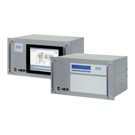
Hardware description - Overview The GC 5000 BTX analyzer is constructed as a 19” plug in case. All necessary parts are integrated as there are • electronic control unit, • PC, heater controller, • gas regulation etc. and • optional equipment as output requirements, calibration gas selector or controller for external devices as permeation modules etc. - Page 15 Fig. 2: Rear view Fig. 3: Gas regulation inside the analyzer Operating Manual GC 5000 BTX; Version 5 – 11/2010...
-
Page 16: Description Of Gc Components
The signal is digitized and analyzed by chromatography software. 3.3.5 Setup of parameters The control software allows to enter and to modify all analysis parameters. Unauthorized access is avoided due to password protection. Operating Manual GC 5000 BTX; Version 5 – 11/2010... -
Page 17: Technical Data Gc 5000 Btx
Stainless steel Internal dimensions H 70 mm x D 80 mm x W 210 mm Heated valve block Temperature controlled, adjustable from 40-150° C Sample valve 6-port VALCO valve, electrically actuated Operating Manual GC 5000 BTX; Version 5 – 11/2010... - Page 18 Developed for optimized connection with GC 5000 Sample stream selector SSM 600, Art.-No. 00001327 Dilution module DIM 200, Art.-No. 00000980 Combustion air supply Dry-running compressor with exchangeable charcoal filter; for FID Art-No. 00000256 Operating Manual GC 5000 BTX; Version 5 – 11/2010...
-
Page 19: Options
Options 3.5.1 Calibration gas selector (optional) The AMA GC 5000 BTX can be equipped with two different calibration gas supplies. 1. Calibration gas generator: The analyzer is equipped with a communication interface to external gas generators. 2. Calibration gas cylinders: Fig. -
Page 20: Optional Modules
Supplied gases Digitally controlled solenoid valves to supply either sample gas, zero gas or calibration gas at sample out port Operating Manual GC 5000 BTX; Version 5 – 11/2010... -
Page 21: Sample Stream Selector Ssm 600
All settings can be saved and loaded together with the analytical method. For effective purging of the sample line a low maintenance membrane pump is optionally available. Operating Manual GC 5000 BTX; Version 5 – 11/2010... - Page 22 Options Low maintenance membrane pump for sample line purging (recommended for sample lines at a length of 5 meters or mores) Order Number Sample stream selector SSM 600, Art.-No. 00001327 Operating Manual GC 5000 BTX; Version 5 – 11/2010...
-
Page 23: Installation
Electrical parts apply voltage while in use. Disregard may result in death, physical injury or damage to property. Therefore make sure that the housing of the GC 5000 BTX is closed before switching on. Caution! Hydrogen is combustible and explosive. Therefore avoid wrong gas connections. -
Page 24: Installation Condition
Hydrogen is combustible and explosive; avoid wrong gas connections. Disregard may result in damage to the system or cause malfunction and wrong detection results. All gas connections to the GC 5000 BTX are labeled. Make sure that the supply of the gases (hydrogen, nitrogen, combustion air) is secured and the correct port for each gas line is used before switching on the system. -
Page 25: Electrical Connections
Electrical parts apply voltage while in use. Disregard may result in death, physical injury or damage to property. Therefore make sure that the housing of the GC 5000 BTX is closed before switching on. Operating Manual GC 5000 BTX; Version 5 – 11/2010... -
Page 26: Start Up And Shut Down
Electrical parts apply voltage while in use. Disregard may result in death, physical injury or damage to property. Therefore make sure that the housing of the GC 5000 BTX is closed before switching on. Caution! Hydrogen is combustible and explosive. Disregard may result in damage to the system or cause malfunction and wrong detection results. -
Page 27: Start Up Instructions
The analyzer is ready for operation after some minutes of warm up. The status color changes from yellow to green (displayed on the screen in the grey bar at the left side down). Operating Manual GC 5000 BTX; Version 5 – 11/2010... - Page 28 (see fig. below). Yellow: the system is not ready as set points of the temperatures have not been reached. Red: An alarm or error has occurred. Operating Manual GC 5000 BTX; Version 5 – 11/2010...
-
Page 29: Decommissioning
Preparation for a saver shipment: If possible, use the original packaging of the analyzer which is purpose-made. (It contains foamed plastic inserts which are adapted to the size of the analyzer.) Operating Manual GC 5000 BTX; Version 5 – 11/2010... -
Page 30: Setting Up The Gc 5000 Software
• The time until the next run will start. Note All commands and functions for setting-up and operating the GC 5000 can be activated via pull-down menus (as described in chapter 11.1.4.) Operating Manual GC 5000 BTX; Version 5 – 11/2010... - Page 31 1. Differing temperature values of the GC oven or detector. This is the case within the first 5 minutes after the system has been powered up. 2. When data acquisition has started, the analyzer is always in the status “not ready”. Operating Manual GC 5000 BTX; Version 5 – 11/2010...
-
Page 32: How To Unlock - Password Protection
If you do not select a password, i.e. the password is empty, you will not have a password protection. In this case the input window will not pop up and the saving of modifications is enabled immediately without protection. Operating Manual GC 5000 BTX; Version 5 – 11/2010... -
Page 33: How To Select Operation Modes
Note It is necessary that both analyzers have the same operation mode, the same number of calibration levels, the same calibration setup and the same validation setup. Operating Manual GC 5000 BTX; Version 5 – 11/2010... -
Page 34: How To Select Communication Parameters
It shows equivalent 0V for 5ppb toluene and 10V for 100ppb toluene. The same is valid for the channels 3, 4 and 5 for the other components. The channels 6 to 8 will not be used. Operating Manual GC 5000 BTX; Version 5 – 11/2010... - Page 35 Fig.5: Connection of analog outputs Operating Manual GC 5000 BTX; Version 5 – 11/2010...
-
Page 36: Alarm Configuration
• Alarm 2 is activated when the concentration of benzene exceeds 10 ppb. • Alarm 3 is activated when the concentration of toluene exceeds 20 ppb. • Alarm 4 is activated when the concentration of m,p-xylene falls below 1 ppb. Operating Manual GC 5000 BTX; Version 5 – 11/2010... -
Page 37: Gesytec Specifications
1200 to 19200 Baud. The default value is „9600“. • The Save value menu makes the inputs active. • With the Quit button you can leave this window without any change. Operating Manual GC 5000 BTX; Version 5 – 11/2010... - Page 38 The following window pops up: The Gesytec II standard allows only 20 results. If more results have to be transmitted the monitoring stations PC must be able to handle them. See chapter 17. Operating Manual GC 5000 BTX; Version 5 – 11/2010...
- Page 39 The following charts show the configuration of the data bytes which can be Protocol bytes sent from the GC 5000 BTX via the Gesytec II protocol. Control byte Start sampling Zero gas on (calibration gas 1)
-
Page 40: Starting Operation
3. If you check “Set time for start” a new input area appears: 4. Enter the time for the start in the 24 hours format, i.e. 18 o’clock means 6 o’clock pm. The analyzer waits until this time and then starts the cycle. Operating Manual GC 5000 BTX; Version 5 – 11/2010... - Page 41 AMA control software after the analyzer has started: When the injection starts, the GC temperature program and acquisition of chromatogram start as well. You can see the real-time chromatogram in the data acquisition window: Operating Manual GC 5000 BTX; Version 5 – 11/2010...
- Page 42 After the chromatogram is completed, you can see the results: Menu bar View Results table All results of the runs are listed: With >copy and paste< you can import the list into an excel file. Operating Manual GC 5000 BTX; Version 5 – 11/2010...
-
Page 43: How To Adjust The Retention Time Windows
2. Menu bar Compare Overlay Mark „Overlay“ in the menu „Compare“. Overlay of all chromatograms: They are listed on top of each other instead of each one in a separate window. Operating Manual GC 5000 BTX; Version 5 – 11/2010... - Page 44 3. Menu bar Compare Synchronize Expansion All overlaid chromatograms can be zoomed the same way at the same time. In this window, the overlay is displayed more comfortable. Operating Manual GC 5000 BTX; Version 5 – 11/2010...
- Page 45 In the lower left corner of the screen you can see an additional window with further instructions. Or alternatively 3. By clicking on Edit Graphic some markers appear in the chromatogram: 4. Enlarge or downsize the retention window by dragging of the blue edge markers. Operating Manual GC 5000 BTX; Version 5 – 11/2010...
- Page 46 Menu bar → → → → File → → → → Save calibration In this case only the retention times are modified not the response values. Operating Manual GC 5000 BTX; Version 5 – 11/2010...
-
Page 47: How To Zoom / Zoom Out The Chromatogram
This activates the new values as well but does not close the window. In this case, you can check first if the new values are ok or modify them again before closing this window. Operating Manual GC 5000 BTX; Version 5 – 11/2010... - Page 48 3. Activate the zoom by clicking the right mouse button. How to zoom You can cancel the zoom by → → → → Right-click into the chromatogram window → → → → Select Undo Expansion Operating Manual GC 5000 BTX; Version 5 – 11/2010...
-
Page 49: How To Optimize Integration Parameters
All possible events with their effects are listed after clicking onto them. 4. Save all adjusted integration parameters: Menu bar → → → → file → → → → Save method Now the system is ready for measuring operation. Operating Manual GC 5000 BTX; Version 5 – 11/2010... -
Page 50: Using Lcd Display And Buttons On The Front Panel
Afterwards the following text appears in the display: First row: informs about the type of analyzer (e.g. GC 5000 BTX). Second row: displays the current program step on the left and on the right about the GC status (ready or not ready). - Page 51 It lists the results of the last run. If there are more than 3 results: scroll the display with the “Up” or “Down” buttons Button “Exit”: Return to the main menu Operating Manual GC 5000 BTX; Version 5 – 11/2010...
- Page 52 Button “Errors”: It lists all errors which were detected. In the example below no error message has been detected. Press “More”: Further error messages are listed if there are any. Operating Manual GC 5000 BTX; Version 5 – 11/2010...
-
Page 53: Calibrating And Validating
Calibrating and validating GC 5000 BTX Calibration 9.1.1 Calibration intervals A GC 5000 BTX needs to be calibrated from time to time. It depends on the stability of the detector: Note Calibration intervals for GC 5000 BTX: By using a FID detector a three month interval is sufficient, with a PID detector a calibration interval once a month is recommended. -
Page 54: How To Enter The Data Of Calibration Gas Concentrations
By contrast a photo ionization detector (PID) does not show a linear detector response. Therefore a minimum of 4 to 5 calibration levels are recommended for proper calibration of the analyzer. Operating Manual GC 5000 BTX; Version 5 – 11/2010... -
Page 55: Enter Data - With A Calibration Gas Module
Note: In case you leave the window by clicking the “Quit” button, the modifications are not saved. 4. When you try to save the new values, the following windows appears first: Operating Manual GC 5000 BTX; Version 5 – 11/2010... - Page 56 By contrast a photo ionization detector (PID) does not show a linear detector response. Therefore a minimum of 4 to 5 calibration levels are recommended for proper calibration of the analyzer. Operating Manual GC 5000 BTX; Version 5 – 11/2010...
-
Page 57: How To Start A Calibration
The calibration of one calibration level is activated. In this example the level is calibrated with the average value of the second and the third run. Operating Manual GC 5000 BTX; Version 5 – 11/2010... -
Page 58: Calibration Of Sequence (Without Calibration Module Or Cal. Valves)
9.3.2 Calibration sequence (without calibration module or cal. valves) The system is configured by AMA Instruments with the following items: o number of runs per level: 1 o the results of the first run is not discarded Setup How to change the pre-configured parameters:... -
Page 59: Auto-Calibration
After the analyzer did the number of selected runs of the first calibration level, it automatically switches to the calibration gas of the next level and does the next runs. The analyzer stops after finishing all runs of the last calibration level. Operating Manual GC 5000 BTX; Version 5 – 11/2010... -
Page 60: Validation
Menu bar Parameters Validation setup This menu item is only activated if the analyzer • is equipped with built-in calibration valves • it has been connected to an external calibration module. Operating Manual GC 5000 BTX; Version 5 – 11/2010... -
Page 61: How To Start Validation
These items select the corresponding inputs when using calibration valves or the corresponding levels when using a calibration module. 4. Select the relevant components for the validation Menu bar Select components Operating Manual GC 5000 BTX; Version 5 – 11/2010... - Page 62 In the window above the following example lists the limits which are defined as warning and error levels for benzene. Zero gas check Warning level 0.3 ppb Error level 0.6 ppb Drift check Warning level Error level Deviation check Warning level Error level Operating Manual GC 5000 BTX; Version 5 – 11/2010...
- Page 63 2. Start an automatic run: Press the “Start” button on the main screen. The validation starts after the specified cycles or time as this parameter have been set in the validation setup. Operating Manual GC 5000 BTX; Version 5 – 11/2010...
- Page 64 • Result of chromatogram for drift check • Name of chromatogram for deviation check • Date and time of chromatogram for deviation check • Result time of chromatogram for deviation check • Drift • Deviation Operating Manual GC 5000 BTX; Version 5 – 11/2010...
- Page 65 • The drift is calculated from the difference from the actual result and the deviation and result from the initial validation. drift: • The deviation is calculated from the difference of two actual results (chromatogram for drift check and chromatogram for deviation check). Operating Manual GC 5000 BTX; Version 5 – 11/2010...
-
Page 66: Functional Description
3. Injection: After enrichment the BTX-tube is heated in a very fast way and the adsorbed materials are vaporized again and flushed onto the capillary column of the gas chromatograph module. Operating Manual GC 5000 BTX; Version 5 – 11/2010... -
Page 67: Definition Of The Program Step
GC column during this program step. Simultaneously the GC temperature program and the data acquisition are started. 8. Cycle time: The cycle time is the time between two starts of sampling. Operating Manual GC 5000 BTX; Version 5 – 11/2010... - Page 68 25 ml/min to 75 ml/min. Standard is 40 ml/min. 12. Chrom Perfect method In this menu item you can select the method for the chromatographic analysis. See chapter 11.4.2.11 for more information about the Chrom Perfect method. Operating Manual GC 5000 BTX; Version 5 – 11/2010...
-
Page 69: Program Example
• 3 minutes (Injection time) later the enrichment tube starts to cool down to the sampling temperature of 30° C and the system is ready for the next start. • This start may occur before the GC oven temperature program was finished. Operating Manual GC 5000 BTX; Version 5 – 11/2010... -
Page 70: Software Reference
The Chrom Perfect software records the chromatograms, analyzes them und passes the results via a file link to the GC 5000 BTX program Note Do never close the Chrom Perfect data acquisition window after switching on the analyzer as the DDE connection between both programs would be broken. -
Page 71: Main Window: Program
An alarm or error message has occurred. A click on the bar informs about the current status details (see next page). Operating Manual GC 5000 BTX; Version 5 – 11/2010... - Page 72 1. Differing temperature values of the GC oven or detector. This is the case within the first 5 minutes after the system has been powered up. 2. When data acquisition has started, the analyzer is always in the status “not ready”. Operating Manual GC 5000 BTX; Version 5 – 11/2010...
-
Page 73: Menu Items
• Unlock • Parameters • Program steps • View • Run calibration • Run validation • Help They are described in detail on the following pages in the following chapters. Operating Manual GC 5000 BTX; Version 5 – 11/2010... -
Page 74: Unlock
The saving of modifications is enabled but without protection. Note Before starting the CP File Editor or CP Analysis “Unlock” has to be activated. Otherwise these menu items are disabled. Operating Manual GC 5000 BTX; Version 5 – 11/2010... -
Page 75: Parameters
• “Cyclic mode”: The analyzer starts the next cycle after the specified cycle time. • “Remote control”: The analyzer waits for a new cycle start via the communication protocol after each run. Operating Manual GC 5000 BTX; Version 5 – 11/2010... -
Page 76: Remote Control
1200 to 19200 Baud. The default value is „9600“. • Clicking on menu item Save value makes the inputs active. • With the Quit button you can leave this window without any change. Operating Manual GC 5000 BTX; Version 5 – 11/2010... - Page 77 1. Select the number of transmitted results: 8, 16, 24, 32, 40 or 48. The Gesytec II standard normally allows only 20 results. If more results are to be transmitted PC of the monitoring stations must be able to handle them. See chapter 17. Operating Manual GC 5000 BTX; Version 5 – 11/2010...
- Page 78 Protocol bytes Protocol The following charts show the configuration of the data bytes which can be bytes sent from the GC 5000 BTX analyzer via the Gesytec II protocol. Control byte Start sampling Zero gas on (calibration gas 1) Span gas on (calibration gas 2)
-
Page 79: Master Mode
Menu bar Parameter Master mode If you have an ozone precursors system (one GC 5000 BTX analyzer and one GC 5000 VOC analyzer) you can switch on the master mode and set the VOC analyzer into slave mode. In this case the BTX analyzer is the master and controls the VOC analyzer (the slave). -
Page 80: Analysis
2. If a value is erroneous (e.g. a temperature value is too low or too high) an error message will occur and the old values will stay active. Operating Manual GC 5000 BTX; Version 5 – 11/2010... -
Page 81: Gc Oven
1. Modify any value by clicking on the relevant input box. 2. Enter the numeric field in the window and press enter “E”. 3. Click on the button „Diagram“ The modified diagram will be displayed: Operating Manual GC 5000 BTX; Version 5 – 11/2010... - Page 82 10° C below the starting temperature of the GC oven program in order to guarantee reliable cooling down of the GC oven at the end of each cycle. Operating Manual GC 5000 BTX; Version 5 – 11/2010...
-
Page 83: Calibration
Another check box appears as there are three possibilities now to run an auto-calibration: • after a specified number of cycles • at a specified time • or when the validation drift check exceeds the warning level Operating Manual GC 5000 BTX; Version 5 – 11/2010... - Page 84 • day and time if necessary. Note The input of the time has to be entered in a 24 hours format, i.e. 10 o’clock pm has to be entered as 22 o’clock. Operating Manual GC 5000 BTX; Version 5 – 11/2010...
- Page 85 Adding com- If you want to add components or levels you have to use the Chrom Perfect ponents /levels File Editor (See chapter 11.3.12 for further information.). Operating Manual GC 5000 BTX; Version 5 – 11/2010...
-
Page 86: Validation Setup
11.3.9 Validation setup Menu bar Parameter Validation setup The following window pops up: Here you can configure all parameters for auto-validations. The validation setup is described in chapter 9.5. Operating Manual GC 5000 BTX; Version 5 – 11/2010... -
Page 87: Analog Output Configuration
It shows equivalent 0V for 5ppb toluene und 10V for 100ppb toluene. The same is valid for the channels 3, 4 and 5 for the other components. The channels 6 to 8 will not be used. Operating Manual GC 5000 BTX; Version 5 – 11/2010... -
Page 88: Alarm Configuration
Note: This concentration must be exceeded / under-run to activate the alarm. If the alarm threshold is 5 ppb and the measurement value is 5 ppb, then the alarm is not activated. Operating Manual GC 5000 BTX; Version 5 – 11/2010... -
Page 89: Cp Analysis
See chapters 7.2 – 7.4 for detailed information. Note Before starting the CP Analysis or CP File Editor the menu item “Unlock” in the menu bar has to be activated. Otherwise these menu items are disabled. Operating Manual GC 5000 BTX; Version 5 – 11/2010... -
Page 90: Cp File Editor
2. For editing a method click on the left upper button, for editing a calibration file click on the right upper button to open a corresponding file. 3. The other file types are not needed. How to edit method files, see next pages. Operating Manual GC 5000 BTX; Version 5 – 11/2010... - Page 91 Events tab: On this tab you can set integration events. This can be easier done in the Analysis module (see chapter 7.4). These parameters are preconfigured by AMA Instruments as well. Operating Manual GC 5000 BTX; Version 5 – 11/2010...
- Page 92 How to determine the threshold: 1. Select context menu measure noise in a real time plot or a loaded chromatogram. The program will tell you the noise and the recommended threshold. Operating Manual GC 5000 BTX; Version 5 – 11/2010...
- Page 93 On this tab you can specify reports which shall be created. Note This part has been already configured by AMA Instruments. Do not modify or delete these two files: last_results2.fmt and results.fmt. They are necessary for a working data transfer to the GC 5000 software!
- Page 94 Plot options tab: On this tab you can configure which details you want to see in a real time plot or in a printed chromatogram. Operating Manual GC 5000 BTX; Version 5 – 11/2010...
- Page 95 • The column “ref. comp.# ” you can select a reference component. Then the retention window of the component is shifted according to a retention time shift of the reference peak. Operating Manual GC 5000 BTX; Version 5 – 11/2010...
- Page 96 • The columns “Level amount” and “Level Response” occur in pairs, one for each level in the calibration file. Operating Manual GC 5000 BTX; Version 5 – 11/2010...
- Page 97 • The two radio buttons (“external / internal standard) determine whether the calibration file will use external or internal calibration. The GC 5000 BTX will always use external calibration. • The Default Component list box determines which component, if any, will be used to quantify peaks that are not identified as components.
- Page 98 This radio button must be set to “Equal weight for all updates” as this is necessary for a correct averaging. Otherwise the result after a calibration with more than two runs per calibration level is not as expected. Operating Manual GC 5000 BTX; Version 5 – 11/2010...
-
Page 99: Module Setup
Menu bar Parameter Module setup In this menu you can configure connected AMA Instruments modules like a sample stream selector, a dilution module or a permeation module. The module setup is described in detail in chapter 9.2.3. Operating Manual GC 5000 BTX; Version 5 – 11/2010... -
Page 100: Program Steps
• Waiting for end of cycle time If the sample program is running, this menu item is disabled. In this case the current program step is always shown real-time on the monitor. Program stopped Operating Manual GC 5000 BTX; Version 5 – 11/2010... - Page 101 Purging of sample line Sampling Waiting for GC Ready Operating Manual GC 5000 BTX; Version 5 – 11/2010...
- Page 102 Injection Waiting for end of cycle time Operating Manual GC 5000 BTX; Version 5 – 11/2010...
-
Page 103: Btx With Stripper Column
• Waiting for end of cycle time If the sample program is running, this menu item is disabled. In this case the current program step is always shown real-time on the monitor. Program stopped Operating Manual GC 5000 BTX; Version 5 – 11/2010... - Page 104 Purging of sample line Sampling Waiting for GC Ready Operating Manual GC 5000 BTX; Version 5 – 11/2010...
- Page 105 Injection Waiting for end of cycle time Operating Manual GC 5000 BTX; Version 5 – 11/2010...
-
Page 106: View
• The reset of alarms as described above. • Standard events like cycle start or program Stop. Use the menu items to save or to print or to clear the event.log file. Operating Manual GC 5000 BTX; Version 5 – 11/2010... - Page 107 Last results Menu bar View Last results This window displays the results of the last cycle. Result Table Menu bar View Results This window displays the results of all cycles. Operating Manual GC 5000 BTX; Version 5 – 11/2010...
- Page 108 It displays the GC ready status: If the status is not ready (status field color is yellow or red), then click on the status field for detailed information. Operating Manual GC 5000 BTX; Version 5 – 11/2010...
-
Page 109: Run Calibration (Manual And Auto-Calibration)
Start. 2. After the analyzer did the number of runs it asks you to connect the next calibration gas to the sample port and press Start again. Operating Manual GC 5000 BTX; Version 5 – 11/2010... - Page 110 Calibration Calibration setup The number of runs per level and if to discard the results of the first run is configured in the calibrations setup. (See chapter 11.3.8 for detailed information). Operating Manual GC 5000 BTX; Version 5 – 11/2010...
-
Page 111: Run Validation
Here you can start a test sample of a calibration level when using a calibration module or an input when using calibration valves. The analyzer stops after the run is completed. Operating Manual GC 5000 BTX; Version 5 – 11/2010... -
Page 112: Help Functions
How to get Clicking onto “Remote support” will start the AMA Remote Support utility. connected: Then AMA Instruments service engineers can connect to the analyzer via Internet and can help you by remote maintenance: 1. Tell us the ID and 2. -
Page 113: Miscellaneous Procedures
The maximum for the cycle time is: 23h 59 min und 59 sec. Change of New temperature set points will be accepted immediately and independent temperature from the current program step. set points Operating Manual GC 5000 BTX; Version 5 – 11/2010... -
Page 114: Programming Gc Oven Parameters
No temperature value is allowed to exceed +210° C. Setting a temperature rate to zero means the temperature program will end at this point and the following parameters will be ignored. Operating Manual GC 5000 BTX; Version 5 – 11/2010... -
Page 115: Select The Parameters For The Running Temperature Program
Total time of GC The total time for the GC oven temperature program is the addition of all oven isotherm and heating times. This value will be updated after pressing the “calculate” button. Operating Manual GC 5000 BTX; Version 5 – 11/2010... -
Page 116: Start And Stop
3. If you check “Set time for start” a new input area pops up: 4. Enter the time for the start in the 24 hours format, i.e. 18 o’clock means 6 o’clock pm. The analyzer waits until this time and starts the cycle automatically. Operating Manual GC 5000 BTX; Version 5 – 11/2010... - Page 117 2. If you press OK the program stops immediately. 3. If you select “Stop when analysis is completed” the analyzer continues completing data acquisition of this chromatogram. One minute later the analyzer stops. Operating Manual GC 5000 BTX; Version 5 – 11/2010...
-
Page 118: Subsequent Data Processing
1. Mark the chromatograms which shall be analyzed and click onto the button Create Sequence file from selected entries 2. Save the sequence file under any name. 3. Menu bar Parameters CP Analysis Start CP Analysis and load any chromatogram. Operating Manual GC 5000 BTX; Version 5 – 11/2010... - Page 119 Is the table already present, then the new results are appended to the end of the old file. With menu bar view results table, the results will be displayed as well in the GC 5000 Software. Operating Manual GC 5000 BTX; Version 5 – 11/2010...
- Page 120 When you double-click onto the traffic light symbol which appeared in the notification area of the PC, a new window pops up in which you can see the progress of the batch processing: Operating Manual GC 5000 BTX; Version 5 – 11/2010...
-
Page 121: Maintenance
The valve oven heater is normally heated up to 80° C (max. 150° C). Disregard may result in third-degree-burns. Adjust the valve oven temperature to 40° C and wait until the heater has cooled down to 40° C Operating Manual GC 5000 BTX; Version 5 – 11/2010... -
Page 122: Maintenance Schedule
On a preventive maintenance basis we recommend to replace the following components at regular intervals. Maintenance work shall only be done by AMA Instruments or by authorized maintenance personnel, i.e. authorized for maintaining and repairing this kind of systems and electrical circuits in accordance with accepted technical safety standards. -
Page 123: Maintenance Work
11. Put the PVC cover onto the cooler again. 12. Plug in the thermocouple plug. The new enrichment tube is inserted. Fig. 7: Exploded view of the Peltier cooler of the enrichment tube Operating Manual GC 5000 BTX; Version 5 – 11/2010... -
Page 124: Maintenance Of The Pump
MFC. Is the filter blocked, it has to be exchanged. Exchange the filter: 1. Loosen the two fittings 2. Pull the filter out of its holder. 3. Put a new filter into the holder 4. Mount the two fittings again. Operating Manual GC 5000 BTX; Version 5 – 11/2010... -
Page 125: Exchange Or Repair The Capillary Column
11. The nuts have to be tightened until the column is not movable in the ferrule anymore. 12. Mount the GC oven cover in reverse order as described above. The new column is inserted. Operating Manual GC 5000 BTX; Version 5 – 11/2010... - Page 126 2. If not, remove the column, re-cut the column, and re-install. A leak-tight connection is formed between the polyimide coating and the fused silica connector. Operating Manual GC 5000 BTX; Version 5 – 11/2010...
-
Page 127: Adjust The Detector Signal
There must be a gap between the case of the glow plug and the electric connector. Otherwise you will have a short circuit between both connections of the glow plug and the ignition might not work. Operating Manual GC 5000 BTX; Version 5 – 11/2010... -
Page 128: Check The Thermocouples
2. Measure the electrical resistance between both pins: It should be between 200Ω and 600Ω if it works properly. 3. Exchange the heating unit if the electrical resistance is indefinite high. Operating Manual GC 5000 BTX; Version 5 – 11/2010... -
Page 129: Exchange Of The Pid Lamp
PID bottom until the two brackets reach their leadings. 10. Do not cant the movable part. 11. Mount the two milled screws again. 12. Connect the cable again. The new PID lamp is inserted. Operating Manual GC 5000 BTX; Version 5 – 11/2010... -
Page 130: Clean The Pid Lamp Window
Disregard may result in third-degree-burns. Adjust the valve oven temperature to 40° C and wait until the heater has cooled down to 40° C Fig. 8: Exploded view of the rotary valve Operating Manual GC 5000 BTX; Version 5 – 11/2010... - Page 131 12. Repeat this step until the preload assembly cannot be tightened anymore by hand. 13. Install the heater again and fix it with the set screw. 14. Mount the valve oven cover. The new rotor is inserted. Operating Manual GC 5000 BTX; Version 5 – 11/2010...
-
Page 132: Exchange The Gc Oven Motor
3. Take out the old fan and put in a new one. 4. Mount the four nuts again and plug in the power cable of the fan. The back panel fan is exchanged now. Operating Manual GC 5000 BTX; Version 5 – 11/2010... -
Page 133: Exchange The Peltier Cooler Fan
Exchange the Teflon O-ring seal. Put the FID top in and mount it with the six screws again. Plug in the two cables. 10. Put on the FID cover. The new FID jet is inserted. Operating Manual GC 5000 BTX; Version 5 – 11/2010... -
Page 134: Troubleshooting
3. The heater element is broken Exchange heater element. 4. Thermocouple is broken and all Software error: 7,8 or 9: refer to status or heaters have to be switched off. event log. Operating Manual GC 5000 BTX; Version 5 – 11/2010... - Page 135 Switch off the monitor with the remote stays black control (green button) and switch it on again with the remote control. 2. The power line of the monitor has Check the according cable. been interrupted Operating Manual GC 5000 BTX; Version 5 – 11/2010...
-
Page 136: Alarm Messages
7. Disconnect the inlet tubing from the in-line filter. 8. Start sampling and check if the sample flow is ok. Result 5: If the sample is too small, the in-line filter has to be replaced. Operating Manual GC 5000 BTX; Version 5 – 11/2010... - Page 137 Result: The signal in the main menu has to be > 100 mV when the PID lamp is on. When the PID lamp is off, the signal has to be < 100 mV. Operating Manual GC 5000 BTX; Version 5 – 11/2010...
- Page 138 Result: The signal in the main menu has to be > 100 mV when the FID flame is lit. In case the flame does not lit, the signal has to be < 100 mV. Operating Manual GC 5000 BTX; Version 5 – 11/2010...
- Page 139 Our Service team will instruct you how to change the fuse. To avoid improper service, this manual does not describe exactly how to change the fuse as the AMA service department should be informed. Operating Manual GC 5000 BTX; Version 5 – 11/2010...
-
Page 140: Warning Messages
(See chapter 14.2 / Alarm 1 for analysis and repair of reached. The the relevant problem). program will be continued!” Operating Manual GC 5000 BTX; Version 5 – 11/2010... -
Page 141: Error Messages
14.4 Error messages The GC 5000 BTX can show 8 different error messages which refer to severe hardware errors within the analyzer. Note! Errors can be only maintained by the manufacturer. Therefore contact AMA Instruments. Besides that first shut down the system and check the communication cables. -
Page 142: Spare Parts List
GC column 1310 GC oven motor 1254 Inlet filter for MFC Maintenance kit FID (FID jet, sealings) 10000 Maintenance kit PID (lamp, centering ring, sealing) 2013 Pump Rotor of the rotary valve Operating Manual GC 5000 BTX; Version 5 – 11/2010... -
Page 143: Warranty
In case of repair during warranty period, it is recommended to provide a detailed and meaningful description of the failure in order to assure a fast repair and to avoid a long-lasting defect analysis. Operating Manual GC 5000 BTX; Version 5 – 11/2010... -
Page 144: Gesytec-Ii Protocol
Telegram identification Monitoring instrument identification (optional) <ETX> End of text <BCC1> Upper nibble <BCC2> Lower nibble If field number 4 is not present, the status of all monitoring instruments (components) is requested. Operating Manual GC 5000 BTX; Version 5 – 11/2010... - Page 145 7 (optional) Operating status Error status Serial number Monitoring instrument ID instrument 8 (optional) Operating status Error status Serial number <ETX> End of text <BCC1> Upper nibble <BCC2> Lower nibble Operating Manual GC 5000 BTX; Version 5 – 11/2010...
-
Page 146: Data Request Da
Error status Serial number Monitoring instrument ID instrument 2 (optional) Measured value ±nnnn±ee Operating status Error status Serial number Monitoring instrument ID instrument 3 (optional) Measured value ±nnnn±ee Operating status Error status Operating Manual GC 5000 BTX; Version 5 – 11/2010... - Page 147 Start of text Length bytes (Upper byte, lower byte) Telegram identification Number of monitoring instruments to transmit data Monitoring instrument ID instrument 1 Measured value ±nnnn±ee Operating status Error status Serial number … Operating Manual GC 5000 BTX; Version 5 – 11/2010...
-
Page 148: Control Command St
Field no. Start byte Data format Field description <STX> Start of text Length byte Telegram identification Monitoring instrument identification Control byte <ETX> End of text <BCC1> Upper nibble <BCC2> Lower nibble Operating Manual GC 5000 BTX; Version 5 – 11/2010... -
Page 149: Appendix
17.8 Appendix Protocol bytes of the AMA Instruments GC5000BTX The following charts show the configuration of the data bytes which can be sent from the AMA GC 5000 BTX Analyzer via the “Gesytec-II” protocol. Control byte Start sampling Zero gas on (calibration gas 1) -
Page 150: Digital I/O
If you have a board with digital inputs and outputs in your analyzer, you can remote-control the analyzer via the digital inputs and read the analyzer’s status and alarms via the digital outputs. The following scheme shows how to connect the inputs and outputs correctly: Operating Manual GC 5000 BTX; Version 5 – 11/2010... -
Page 151: Digital Outputs
9. Alarm 1 – 4 These four outputs are for high alarms or low alarms for monitored components. You can configure the alarms in the alarm configuration window (see chapter 11.3.11) Operating Manual GC 5000 BTX; Version 5 – 11/2010... -
Page 152: Digital Inputs
8. Start initial validation You can start an initial validation with this input. 9. Start standard validation You can start a standard validation with this input. Operating Manual GC 5000 BTX; Version 5 – 11/2010...
Need help?
Do you have a question about the GC 5000 BTX and is the answer not in the manual?
Questions and answers