Table of Contents
Advertisement
Available languages
Available languages
Quick Links
VULCANIC S.A.S.
48, rue Louis Ampère – Zone Industrielle des Chanoux
F – 93330 NEUILLY SUR MARNE
Tél. : +33 (0)1 49 44 49 20 – Fax : +33 (0)1 49 44 49 41
E-mail : catalogue-vulcanic@vulcanic.com
Web : www.vulcanic.com
NOTICE D'INSTRUCTIONS
THERMOPLONGEUR À VISSER
TYPE 2300
OPERATING INSTRUCTION
SCREW IMMERSION HEATER
TYPE 2300
UT 81086.01 -C - FR/EN page 1 sur 18
Advertisement
Table of Contents

Related Manuals for VULCANIC 2300


Summary of Contents for VULCANIC 2300
- Page 1 VULCANIC S.A.S. 48, rue Louis Ampère – Zone Industrielle des Chanoux F – 93330 NEUILLY SUR MARNE Tél. : +33 (0)1 49 44 49 20 – Fax : +33 (0)1 49 44 49 41 E-mail : catalogue-vulcanic@vulcanic.com Web : www.vulcanic.com NOTICE D'INSTRUCTIONS THERMOPLONGEUR À VISSER TYPE 2300 OPERATING INSTRUCTION SCREW IMMERSION HEATER TYPE 2300 UT 81086.01 -C - FR/EN page 1 sur 18...
- Page 2 VULCANIC devra être contactée si certains documents cités dans le présent manuel ne sont pas disponibles, ou si les informations qui y figurent ne pa- raissent pas claires. Si nécessaire, un technicien de chantier VULCANIC devra être sollicité pour la mise en service.
-
Page 3: Domaine D'utilisation
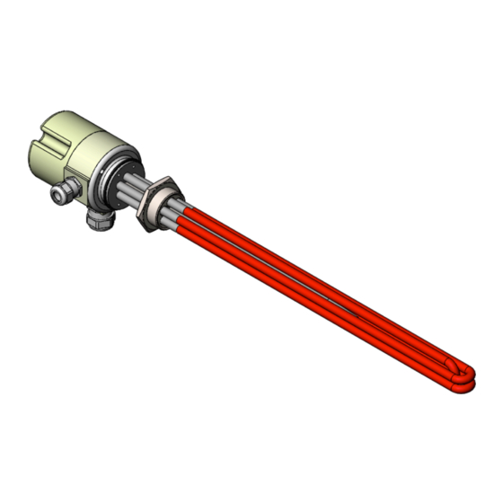
DOMAINE D'UTILISATION Ce matériel est conçu pour chauffer des fluides stagnants ou circulants (liquides ou gaz), en inté- rieur ou à l'extérieur, en ambiance protégée et non explosible (à l'abri du soleil, pour une tempéra- ture ambiante comprise entre 5 °C et 40 °C avec une humidité relative 90% maximum sans ruis- sellement). -
Page 4: Montage Et Raccordement
Dans le cas d’un liquide, monter le thermoplongeur de telle manière que la partie chauffante soit constamment immergée. Dans le cas contraire, il y a des risques de surchauffe et de destruction de l’équipement, effectuer une purge afin de supprimer les poches d’air avant la mise sous tension et surveiller en continu le niveau du liquide. - Page 5 Montage Privilégier le montage horizontal (± 15°). En cas de montage vertical, placer de préférence le boîtier de raccordement en partie basse. En cas de montage vertical avec le boîtier en partie haute, surveiller la température de ce boîtier. Dans le cas particulier du chauffage d'un liquide, respecter les précautions d'emploi relatives à...
- Page 6 Raccordement électrique Réaliser la connexion de l'alimentation et du dispositif de sécurité conformément au schéma fourni (voir documentation contractuelle). Ce schéma est collé à l'intérieur du boitier, en son ab- sence, veuillez contacter le service après-vente via le formulaire de contact de notre site internet. Connecter au moins l'une des bornes de masse à...
-
Page 7: Entretien
Mise en service En cas de stockage prolongé ou d’arrêt de l’installation, avant la mise en route, vérifier l’intégrité du matériel, notamment l’isolement électrique et le bon fonctionnement des organes de protection. Le montage de l’élément chauffant et la première mise en service doivent être faits par un technicien assumant la responsabilité... -
Page 8: Garantie
échappent à notre contrôle, Notre matériel, les normes et directives étant en constante amélioration cette fiche peut être modi- fiée sans préavis et les caractéristiques indiquées par les textes et les images n’engage la société VULCANIC qu’après confirmation par nos services. UT 81086.01 -C - FR/EN page 8 sur 18... - Page 9 UT 81086.01 -C - FR/EN page 9 sur 18...
- Page 10 SCHÉMAS DES THERMOSTATS ET SONDES RÉGULATEUR OU CONTRÔLEUR DE THERMOSTAT TEMPÉRATURE À RÉARMEMENT MANUEL THERMOSTAT À RÉARMEMENT 3 CONTACT SIMPLE À AUTOMATIQUE OUVERTURE 1 CONTACT INVERSEUR LIMITEUR DE TEMPÉRATURE THERMOSTAT À RÉARMEMENT THERMOCOUPLE J MANUEL 1 CONTACT SIMPLE À OUVERTURE LIMITEUR DE TEMPÉRATURE THERMOSTAT...
-
Page 11: Area Of Use
AREA OF USE This equipment is designed to heat standing or circulating fluids (liquids or gases), inside or out- side in a non-potentially explosive environment (sheltered from the sun, at an ambient temperature of 5°C to 40°C, and with a maximum relative humidity of 90% without run-off). Its detailed technical data and limits of use are stated in the contractual documentation, and its number appears on the nameplate, order acknowledgement and delivery note (reference, type, specification or drawing). -
Page 12: Assembly And Connection
Bleed in order to remove any pockets of air before the heater is switched on, and monitor the level of liquid continuously. If fitted inside a heater in operation, check the direction of flow and as a min- imum, install a bleeder, valve and flow controller to address any pockets of gas that may form dur- ing use. - Page 13 please monitor the temperature of the box. In the special case of heating a liquid, observe the pre- cautions for use concerning immersion of the heating element. Ensure the immersion heater is properly tightened according to the material of the sealing gasket supplied, and that of the plug and the attachment interface: Plug/attachment interface material Dimensions...
-
Page 14: Switch-On Procedure
Connect the electricity supply and the safety device as shown in the diagram supplied (see contractual documentation). This diagram is pasted inside the box, in its absence, please contact the after-sales service via the contact form on our website. Connect at least one of the earth terminals to the installation earth. Ensure the connections are adequately tightened (2.5 N.m for M4 terminals, 3 N.m for M5 terminals, and 3.5 N.m for M6 terminals). -
Page 15: Maintenance
Power up the immersion heater. Check that the line current complies with the expected val- With forced convection heating of liquid or gas, make sure that a reduction in the flow to be- low the minimum threshold provided for by the thermal transfer calculations imperatively stops the heater's operation. -
Page 16: Warranty
Since standards, directives and our equipment are continuously updated, this sheet may be amended without notice; the features indicated in the text and images it contains are only binding upon VULCANIC following confirmation by the company. UT 81086.01 -C - FR/EN page 16 sur 18... - Page 17 STAR SERIES DELTA SERIES SINGLE SERIES COUPLING COUPLING COUPLING (2 components in series) (2 components in series) STAR PARALLEL DELTA COUPLING SINGLE PARALLEL COUPLING COUPLING COUPLING (2 components in parallel) (2 components in parallel) UT 81086.01 -C - FR/EN page 17 sur 18...
- Page 18 DIAGRAMS OF THERMOSTATS AND SENSORS TEMPERATURE CONTROL OR REGULATOR THERMOSTAT WITH MANUAL THERMOSTAT RESET WITH AUTOMATIC RESET 3 SINGLE CONTACTS 1 CHANGEOVER AT OPENING CONTACT TEMPERATURE LIMITER THERMOSTAT WITH MANUAL THERMOCOUPLE J RESET 1 SINGLE CONTACT AT OPENING TEMPERATURE LIMITER THERMOSTAT THERMOCOUPLE K WITH MANUAL...
Need help?
Do you have a question about the 2300 and is the answer not in the manual?
Questions and answers