Table of Contents
Advertisement
Available languages
Available languages
Quick Links
VULCANIC S.A.S.
48, rue Louis Ampère – Zone Industrielle des Chanoux
F – 93330 NEUILLY SUR MARNE
Tél. : +33 (0)1 49 44 49 20 – Fax : +33 (0)1 49 44 49 41
E-mail : catalogue-vulcanic@vulcanic.com
Web : www.vulcanic.com
NOTICE D'INSTRUCTIONS
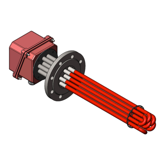
THERMOPLONGEUR SUR BRIDE
TYPE 2400
OPERATING INSTRUCTION
FLANGE IMMERSION HEATER
TYPE 2400
81086.02 – C - FR/EN- page 1 sur 17
Advertisement
Table of Contents

Subscribe to Our Youtube Channel
Related Manuals for VULCANIC 2400


Summary of Contents for VULCANIC 2400
- Page 1 VULCANIC S.A.S. 48, rue Louis Ampère – Zone Industrielle des Chanoux F – 93330 NEUILLY SUR MARNE Tél. : +33 (0)1 49 44 49 20 – Fax : +33 (0)1 49 44 49 41 E-mail : catalogue-vulcanic@vulcanic.com Web : www.vulcanic.com NOTICE D'INSTRUCTIONS THERMOPLONGEUR SUR BRIDE TYPE 2400 OPERATING INSTRUCTION FLANGE IMMERSION HEATER TYPE 2400 81086.02 – C - FR/EN- page 1 sur 17...
- Page 2 VULCANIC devra être contactée si certains documents cités dans le présent manuel ne sont pas disponibles, ou si les informations qui y figurent ne parais- sent pas claires. Si nécessaire, un technicien de chantier VULCANIC devra être sollicité pour la mise en service.
-
Page 3: Domaine D'utilisation
DOMAINE D'UTILISATION Ce matériel est conçu pour chauffer des fluides stagnants ou circulants (liquides ou gaz), en intérieur ou à l'extérieur, en ambiance protégée et non explosible (à l'abri du soleil, température am- biante de 5 °C à 40 °C, humidité relative 90% maximum sans ruissellement). Ses caractéristiques techniques et limites d'utilisation détaillées figurent dans la documenta- tion contractuelle, dont le numéro est repris sur la plaque signalétique, sur l'accusé... -
Page 4: Montage Et Raccordement
surveiller en continu le niveau du liquide. Dans le cas d’un montage dans un réchauffeur en circula- tion, vérifier le sens de circulation, installer à minima une purge et un contrôleur de débit ainsi qu’une soupape en cas de création de poche de gaz lors de l’utilisation. Dans le cas d’un chauffage de gaz, il est obligatoire de contrôler en permanence le débit du gaz à... - Page 5 Montage Privilégier le montage horizontal (± 15°). En cas de montage vertical, placer de préférence le boîtier de raccordement en partie basse. En cas de montage vertical avec le boîtier en partie haute, surveiller la température de ce boîtier. Dans le cas particulier du chauffage d'un liquide, respecter les précautions d'emploi relatives à...
- Page 6 Se reporter aux différents schémas de câblages disponibles. Attention à bien tenir compte de la tension unitaire des épingles. Pour éviter tout risque d'erreur, vérifier la position des circuits (en croix ou en cercle ou paral- lèle) avant de réaliser le couplage suivant les schémas joints. Pour les thermoplongeurs, nous fournissons en option des barrettes de couplage spéciale- ment étudiées (voir notre catalogue).
-
Page 7: Entretien
5.2.1 Dans le cas de la présence d’un régulateur Régler le thermostat à la température désirée. Avant stabilisation à la température nominale d’utilisation, s'assurer du bon fonctionnement du thermostat de régulation : la manœuvre de son bouton de réglage doit provoquer l'arrêt du chauf- fage et sa remise en route. -
Page 8: Garantie
échappent à notre contrôle, Notre matériel, les normes et directives étant en constante amélioration cette fiche peut être modifiée sans préavis et les caractéristiques indiquées par les textes et les images n’engage la so- ciété VULCANIC qu’après confirmation par nos services. 81086.02 – C - FR/EN- page 8 sur 17... - Page 9 81086.02 – C - FR/EN- page 9 sur 17...
-
Page 10: Area Of Use
AREA OF USE SCHÉMAS DES THERMOSTATS ET SONDES RÉGULATEUR OU CONTRÔLEUR DE TEMPÉRATURE THERMOSTAT À RÉARMEMENT THERMOSTAT MANUEL À RÉARMEMENT 3 CONTACT SIMPLE AUTOMATIQUE À OUVERTURE 1 CONTACT INVERSEUR LIMITEUR DE TEMPÉRATURE THERMOSTAT THERMOCOUPLE À RÉARMEMENT MANUEL 1 CONTACT SIMPLE À OUVERTURE LIMITEUR DE TEMPÉRATURE... -
Page 11: Precautions For Use
This equipment is designed to heat standing or circulating fluids (liquids or gases), inside or outside in a non-potentially explosive environment (sheltered from the sun, at an ambient temperature of 5°C to 40°C, and with a maximum relative humidity of 90% without run-off). Its detailed technical data and limits of use are stated in the contractual documentation, and its number appears on the nameplate, order acknowledgement and delivery note (reference, type, specification or drawing). -
Page 12: Assembly And Connection
mum, install a bleeder, valve and flow controller to address any pockets of gas that may form during use. If the appliance is heating gas, the flow of the gas to be heated must be monitored at all times. Pay particular attention when the electricity supply is switched off –... - Page 13 monitor the temperature of the box. In the special case of heating a liquid, observe the precautions for use concerning immersion of the heating element. Where distance A is greater than 1,000 mm: fitting and removal will need to be facilitated by installa- tion of a guide or support cradle designed to avoid damage to the shielding.
-
Page 14: Switch-On Procedure
For all configurations: When selecting the connection cable, take into account that the temperature in the connection box can be approx. 20° to 50°C higher than that of the external environment. Avoid placing the power supply against the connection wire from the safety device (low volt- age) inside the same sheath. -
Page 15: Maintenance
Since standards, directives and our equipment are continuously updated, this sheet may be amend- ed without notice; the features indicated in the text and images it contains are only binding upon VULCANIC following confirmation by the company. 81086.02 – C - FR/EN- page 15 sur 17... - Page 16 81086.02 – C - FR/EN- page 16 sur 17...
- Page 17 SINGLE SERIES COUPLING STAR SERIES COUPLING DELTA SERIES COUPLING SINGLE PARALLEL COUPLING STAR PARALLEL COUPLING DELTA SINGLE PARALLEL COUPLING DIAGRAMS OF THERMOSTATS AND SENSORS TEMPERATURE CONTROL OR REGULATOR THERMOSTAT WITH MANUAL THERMOSTAT RESET WITH AUTOMATIC RESET 3 SINGLE CONTACTS 1 CHANGEOVER AT OPENING CONTACT TEMPERATURE...
Need help?
Do you have a question about the 2400 and is the answer not in the manual?
Questions and answers