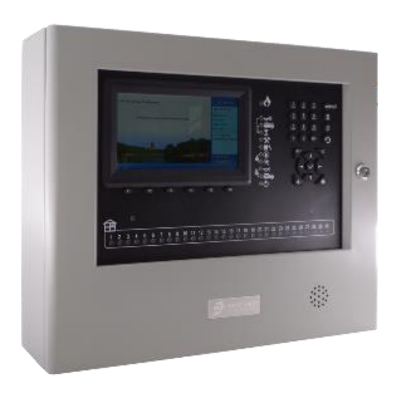
Jade Bird JBE-P2L1 Installation & Operation Manual
Hide thumbs
Also See for JBE-P2L1:
- Installation & operation manual (56 pages) ,
- Quick manual (2 pages)

Related Manuals for Jade Bird JBE-P2L1


Summary of Contents for Jade Bird JBE-P2L1
- Page 1 JBE-P2L1 Draco Fire Control Panel Installation & Operation Manual M-P2L1-1 EN Release Date: November 15, 2019 Rev 01...
- Page 2 This manual is protected by copyright © 2019 Jade Bird Fire Alarm with all rights reserved. Draco and Lyra 21 Series are trademarks of Jade Bird Fire Alarm. Manufacturer Jade Bird Fire Alarm International (Europe), S.L. Carrer de Tarragona 157 7-2, 08014 Barcelona, Spain REV 01.
-
Page 3: Table Of Contents
Power supply ............................4 Batteries..............................4 Product range and compatibility ......................5 Panel’s optional modules ......................... 6 3.1.5.1 Second loop card (JBE-P2L1-EXLP) ........................6 3.1.5.2 Printer (JBE-PRT) ..............................6 3.1.5.3 External battery box for 17 Ah batteries (JBE-BAT) ....................6 INSTALLATION .............................. - Page 4 5.3.2.6 View zone status ..............................25 5.3.2.7 View device status .............................. 25 5.3.2.8 View addresses used in a loop ........................... 26 5.3.2.9 View address descriptions ..........................26 5.3.2.10 View system composition and date of last configuration ................26 5.4................27 PERATIONS AVAILABLE TO USERS WITH ACCESS EVEL AND ABOVE...
- Page 5 MAINTENANCE .............................. 43 7.1............................43 LANNED MAINTENANCE Periodic inspections & maintenance ...................... 43 Battery Maintenance ..........................43 Cleaning ..............................43 7.2..................43 ORRECTIVE MAINTENANCE PERATION IN CASE OF FAULT Indication of common faults ........................44 Indication of faults affecting SND or FB outputs..................44 Indication of earth faults.
-
Page 6: Introduction
Introduction This manual contains the information and the instructions required to install, commission, operate and maintain the JBE-P2L1 (Draco) fire control panel. Only trained professionals should attempt to install this panel. An incorrect installation may not provide the performance expected from fire safety devices. - Page 7 Redundant class-A loop integrity monitoring and self-healing The addressable loops of the Draco panel can be connected in stubs (class B) or looped (class A) topologies. When more than 32 initiating devices are connected to the loop, class A topology shall be used and JBE- 2150 isolators shall be installed in the loop to limit the consequences of a short circuit in the loop.
-
Page 8: Additional Ancillary Functions
C. Tarragona, 157. 08014 Barcelona (Spain) DoP-0370-CPR-3813-1 EN 54-2 , EN 54-4 JBE-P2L1 Draco Fire Control Panel Technical file: see TF-JBE-P2L1-10 provided by the manufacturer. Jade Bird Fire Alarm International (Europe), S.L. C. Tarragona, 157. 08014 Barcelona (Spain) www.jadebird.eu.com M-P2L1-1 EN... -
Page 9: Technical Specifications
Technical Specifications This chapter will review the technical specification and provide detailed data on the overall system, and the electrical, mechanical and environmental characteristics of the Draco fire control panel. General Data Table 1: General Panel Data System dimensions Number of detection loops 1 or 2 User-selectable detection loop topologies Class A (ring) or Class B (stub) -
Page 10: Product Range And Compatibility
Product range and compatibility The following chart contains the list of products from Jade Bird Europe which are compatible with the Draco fire panel. Table 2: Compatible Product Range Loop devices JBE Code EN 54-11 Manual Call Point JBE-2100 EN 54-5 Heat detector with remote indicator output... -
Page 11: Panel's Optional Modules
Second loop card (JBE-P2L1-EXLP) The second loop card (JBE-P2L1-EXLP) can be added to the main loop card to expand the panel into a two (2) loop panel. The second loop has the same capabilities as the first loop in the number of devices and power limits. -
Page 12: Installation
Installation This chapter provides the necessary information and guidelines for the installation of the Draco fire control panel. Installation of this product shall only be conducted by trained professionals. Installation by personnel other than trained experienced electrical technicians may impact the overall performance of the system. Voltage –... -
Page 13: Planning Wire Topology To Meet En 54-2 Requirements On Integrity Of Transmission Paths
Note that the Main panel, the printer box and the battery box stack together. Therefore, when these 3 parts are used, the total dimensions of the assembly are (WxHxD) = 440x740x126 mm and a total weight of 19 kg (including 2x17 Ah batteries). The accessory modules are not intended to be installed separate from the main fire panel. -
Page 14: Physical Mounting Instructions
5. Use the 2x provided nuts to fasten the printer to the panel’s main housing. Tighten firmly. 6. Route the provided flat ribbon cable through to the opening between the panel and the printer. 7. Connect the flat ribbon cable to connector J3 in the panel’s display board (PCB JBE-P2L1 DP) and to the printer. -
Page 15: Mounting To The Wall
Mounting to the wall 1. Before starting installation, verify that the wall at the desired location is appropriate and suitable for the weight and environmental requirements of the panel. 2. Based on Figure 2, verify the clearance around the panel in the desired area and measure the location of the centering hole on the wall. - Page 16 4. With the batteries removed, hang the panel from the screw on the wall by passing it through the central keyhole in the back of the panel. 5. From this position, level the panel and mark the mounting hole locations: a.
-
Page 17: Electric Wire Connections
Electric wire connections The door of the fire panel protects ordinary users from electric risks. The door of the fire panel must be kept closed, locked and with the key removed. Access to the fire panel’s interior shall be restricted to instructed users. - Page 18 3. With the panel secure, run the mains power line into the panel and secure it to the provided mains terminal block. Figure 6: Mains Connections This equipment must always be earthed 4. Secure all incoming wires to the cabinet with the provided tie wraps. Figure 7: Illustration of Secured Wiring M-P2L1-1 EN Page 13...
-
Page 19: Fitting The Batteries
Fitting the batteries This product shall be used only with the approved battery types shown. Note that the appropriate battery size depends on whether the optional battery box JBE-BAT has been installed or not: a) System with primary cabinet only (6.3 mm Faston tab terminals) •... - Page 20 2) Insert the batteries as shown in the pictures below. 3) Insert again the battery holder brackets. Tighten screws thoroughly. 4) Connect the battery cable terminals 5) Verify the temperature sensor is placed near the batteries to provide adequate temperature feedback to the charging circuit.
-
Page 21: Commissioning Using The Wizard
4.3. Commissioning using the Wizard The Draco fire panel features a commissioning wizard. This wizard will guide the installer step-by- step to achieve a functional basic configuration. More sophisticated configurations can be achieved by exercising the configuration options described in section 5.5. The commissioning operations are restricted to user access level 3 and shall be conducted by trained operators only. -
Page 22: Operation Instructions
Operation instructions 5.1. General indications This chapter will provide detailed instructions on how to operate the fire control panel. The same user interface in the panel will provide incremental functionality for each user access level. Read the instructions carefully before attempting to operate the panel. Visual indications The Draco fire control panel provides eleven (11) system status LED indicators and a keypad consisting of a total of thirty-one (31) soft function keys. - Page 23 Table 4: LED Indicators Icon next to LED name Color Status Indication the LED Steady Fire alarm The panel is in “Fire alarm” state Steady The sounder outputs are ON Sounders ON The sounder outputs are in delayed Blinking activation and will activate automatically after the delay time has expired.
-
Page 24: Lcd User Interface
5.1.1.2 LCD user Interface The Fire panel’s LCD screen provides multiple windows, which will present information prioritized depending on the type of events detected in the system. The same LCD screen will be used to present the end user with menu options. The screen is segmented in the following windows (shown in Figure 12): 1) Permanent system status window. -
Page 25: Control Keys
Control Keys The Draco panel features soft buttons and alphanumeric keys which allow users to navigate the system directly from the keypad, even when they are wearing work gloves. Figure 13: Control Keys Figure 14: Function Keys M-P2L1-1 EN Page 20 Release Date: November 15, 2019 Rev 01... - Page 26 Table 5: Control Keys Function Icon Description Silence sounders when they are active Re-activate sounders after they have been silenced Sounders OFF / re-sound Override sounder’s delay, when they are in delayed activation state. Delay on/off/override Activate/deactivate the output delays Buzzer silence Silences/mute the buzzer of the fire panel Resets the active events and returns the fire panel to...
-
Page 27: Acoustic Warnings
Acoustic Warnings The panel will send out the following acoustic signals to notify the user about the occurrence of significant events in the panel. Note that the alarm signal takes precedence over the fault signal. Table 6: Fire Panel Acoustic Annunciators Buzzer signal Description Fast beep: The buzzer sounds 3 times per second... -
Page 28: Operations Available To All Users (Access Level 1 And Above)
5.3. Operations available to all users (access level 1 and above) This chapter describes the functionality accessible to the building’s first responders, who are considered a general public user with training and responsibility for initial investigation of incidents related with the fire system. -
Page 29: View Faults
5.3.2.1.2 Alarms Press 2 to enter the sub-menu Alarms. All the Alarm events are displayed chronologically from newest to oldest. F1 stands for the number of the output group, press F2 to return to the first page, press F3 to print out the event log (if the optional printer is attached), press F4 to return to the previous page, press F5 scroll down to the next page, press F6 to exit the current interface. -
Page 30: View Disablements
5.3.2.3 View disablements Use this menu to obtain a description of the active disablements. Press F1 to return to the first page, press F2 to view previous page, press F3 to view next page, press F4 to page up, press F5 to page down, press F6 to exit. 5.3.2.4 View zones under test This menu will show the list of zones which are under test mode. -
Page 31: View Addresses Used In A Loop
5.3.2.8 View addresses used in a loop Press the Home key and then F1, press 8 to enter the menu View addresses used in a loop. Manually enter the loop number from the numeric keypad, press either F2 or F3 to change the loop the user would like to access. -
Page 32: Operations Available To Users With Access Level 2 And Above
5.4. Operations available to users with access Level 2 and above This chapter describes the functionalities of the panel that an operator with user access level 2 can operate. This level of access is normally granted to users trained in the usage of fire systems. The operator level is restricted by a three-digits password, the default password to access this level is 111. -
Page 33: Test Output Group
5.4.3.2 Test output group This menu allows testing the activation of an output group. A test will activate temporarily all the output devices associated to a group. After entering user access level 2 password, enter test output group from operate menu. The operator can select a specific output group (sounder group, fire routing group) from the main sub-menu by entering in a 1 for yes using the directional keys and the numeric keypad. -
Page 34: Set Time
The panel will remain in disabled functional condition as long as there is one disabled device or zone. 5.4.3.8 Set time Enter the Set time menu to adjust the date and time of the panel by using the numeric and directional keypads, press F1 to clear the data, F5 to confirm and F6 to exit. -
Page 35: Save Configuration Or Event Log To Usb
5.4.4.2 Save configuration or Event log to USB Under this function, the operator can upload/copy the configuration of the panel and event log to the USB by selecting the listed options: Load descriptions • Load registration info • Load zone info from USB •... -
Page 36: Operations Available Only To Users With Access Level 3
5.5. Operations available only to users with access level 3 This section describes in detail what functionalities of the panel that a user access level 3, either installer or maintenance/commissioning personal, can have. For this user access level, the menus for Adjust and Install are available. -
Page 37: Delays And Linkage Of Snd/Fb By Zone
5.5.1.4 Delays and linkage of SND/FB by zone Under this sub-menu, users can program/set the delay on either sounder and fire routing for all zones or set sounder and fire routing delay separately by zone. User can also link/unlink either sounders or fire routing per zone. -
Page 38: Assign Device To Activation Group
5.5.1.6 Assign device to activation group Under this sub-menu, user can assign each output device to designated group in activation. In this menu, the currently assigned output group for each device is listed under the “Current” column. Note the following pre-assigned output groups: Group 001: Sounders Group 002: Fire Routing Groups 003-400: Groups freely programmable in “advanced configuration”... - Page 39 Figure 16: Day/Night Mode Push “F3” to configure the desired sensitivity level of each detector for each profile. Refer to the detector’s datasheet to understand the details of each sensitivity level. Figure 17: Detector Sensitivity Selection M-P2L1-1 EN Page 34 Release Date: November 15, 2019 Rev 01...
-
Page 40: Set Printer
5.5.1.10 Set Printer The printer is an optional accessory to the panel. If the user doesn’t require or need the additional printer box, in that case the printer configuration is not necessary. When the user chooses to add the additional printer box, the installer needs to configure the printer upon installation. -
Page 41: Set Special Operation Mode
5.5.2.5 Set special operation mode From this sub-menu, users can select the operation mode from either the EN 54 compliant mode or a commissioning mode to extend the screen timeout during installation. The panel supports two operating modes: A general operation mode and a commissioning mode. In commissioning mode, the menu screen timeouts are extended for convenience of the technicians. - Page 42 Figure 18: Example Input Action 5.5.2.6.2 Programming the “Outputs” triggered by an action Up to 8 output groups can be activated by a single action. This includes the sounder (SND-001) and Fire Routing (FR-002) output groups. For each activation, enter the following parameters Activation group: Select the group to activate when the input rule is fulfilled.
- Page 43 Figure 19: Example Output Action 5.5.2.6.3 Reviewing the action Once an action’s programming has been entered into the panel configuration, it can be reviewed in a single screen with the coding below: Input scenarios combination = Output programs triggered Where the input scenarios are coded as S(Zone, alarm type, quantity) and the programmed outputs programmed are coded as P(group number, delay, hold ).
-
Page 44: Clear
Figure 20: Advanced Programming Example 5.5.2.6.5 EN 54 Type “C” coincidence detection The coincidence detection specified in EN 54 is a particular case of the advanced programming shown in this section. In type “C” coincidence detection, the panel enters into alarm functional condition at the reception of a first alarm. -
Page 45: Usb Firmware Update
5.5.2.8 USB firmware update Users can update the firmware of the panel by using a USB memory drive. The usb bay is located in the interior of the fire panel. Once the USB is plugged in, users can choose the type to upgrade from either normal or commissioning and to update either panel or image. -
Page 46: Operation In Case Of Alarm
Operation in case of alarm When the Draco fire panel receives an alarm, it will automatically: Indicate it audibly with the buzzer alarm indication • Activate the general fire alarm indication • Present the alarm screen • Activate the fire relay and initiate the pre-programmed output activation sequence. •... -
Page 47: Output Activation - Delay Override
Figure 21: Fire Alarm Screen 6.3. Output activation – delay override In the event of fire alarm, all outputs will activate as programmed automatically. That is, without any manual intervention. There is a special case where sounders or fire routing outputs have a programmed delay configured. In this case, upon reception of an alarm, the fire panel will enter the “delayed activation”... -
Page 48: Maintenance
Maintenance 7.1. Planned maintenance Periodic inspections & maintenance Most of local or regional fire regulations require that fire systems undergo periodic inspections performed by professionals. Contact a local specialized installation or maintenance company to execute the code- mandated inspections and ensure the panel is inspected at least quarterly. The Draco fire panel has a rich feature set to support and shorten site inspections: Under the “View”... -
Page 49: Indication Of Common Faults
Indication of common faults Each loop device has a unique address composed by the loop number and loop address. Installers can also assign a text description to each loop device (i.e.: “MCP in the kitchenette”). In case a fault is processed for any loop device, this information will be presented in the main screen and it will be added to the event log. -
Page 50: Menu Tree Structure
Menu Tree Structure 8.1. View menu (User access level 1) Table 8: Menus accessible to user access Level 1 User access level 1 (no password) and above Menu level 1 Menu level 2 Menu level 3 View menu 1. View event log 1. -
Page 51: Adjust & Install Menus (User Access Level 3)
2. Installer password 1. Spanish 2. English 4. Set language 3. Catalan 4. Engineering language Install menu 1. JBE-P2L1 EN 54 5. Set special operation mode 2. Commissioning 6. Enter advanced programming 1. Clear descriptions 2. Clear all zone info 7. Clear 3. -
Page 52: List Of Tables
List of Tables Table 1: General Panel Data .......................... 4 Table 2: Compatible Product Range ......................5 Table 3: Mechanical Dimensions ........................7 Table 4: LED Indicators ..........................18 Table 5: Control Keys ........................... 21 Table 6: Fire Panel Acoustic Annunciators ....................22 Table 7: Access Levels and Passwords ....................... -
Page 53: List Of Figures
10 List of Figures Figure 1: EN 54 Loop Topology Options ......................8 Figure 2: Mounting Holes ..........................10 Figure 3: First screw for center keyhole ....................... 10 Figure 4: Mounting Hole Locations ....................... 11 Figure 5: Loop Board Connections ....................... 12 Figure 6: Mains Connections ........................
Need help?
Do you have a question about the JBE-P2L1 and is the answer not in the manual?
Questions and answers
how to put delay in controll module
The JBE-P2L1 fire panel allows scheduled activation and deactivation of delays. These delays can be set manually or programmed based on a schedule. To add a delay in the control module, follow these steps:
1. Access the panel's settings.
2. Navigate to the delay configuration section.
3. Set the desired delay time for activation or deactivation.
4. Assign the delay to specific detectors if needed.
5. Save the settings.
The system allows independent sensitivity settings and scheduled delays, which can be manually overridden if required.
This answer is automatically generated