Advertisement
Quick Links
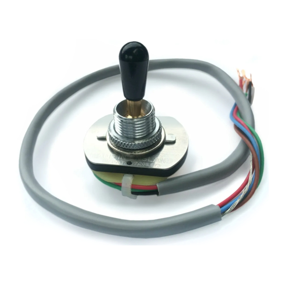
The 3X3-07 Model has three pairs of link pads: L1 L2 & L3
These are used to configure the switch for different functions.
abridge pads with solder only where indicated. Do this
1
4
3X3-07
Free-Way Switch
Model No:-
With reference to the individual scheme diagram, carefully
before installing in the guitar and avoid using excess solder.
(Note: 7 interlinking wires are omitted in this view for clarity).
12mm
16mm
32mm
2
3
6
5
257mm
Last Updated Jul 2017
Note: Greyed connections in position 5 are only made when both L1 and L2 are closed.
Note: When L3 is closed, the shield wire is conected to the green wire in positions 1 2 & 3.
Shield Wire (Chassis)
White Wire
Red Wire
Black Wire
Blue Wire
Green Wire
Brown Wire (Bridge Tap)
4.3mm
(Neck Hot)
(Output)
(Bridge Hot)
(Neck Tap)
(Com)
6mm
70mm
Schematic
Advertisement

Related Manuals for Free-Way Switch 3X3-07


Summary of Contents for Free-Way Switch 3X3-07
- Page 1 The 3X3-07 Model has three pairs of link pads: L1 L2 & L3 These are used to configure the switch for different functions. With reference to the individual scheme diagram, carefully abridge pads with solder only where indicated. Do this before installing in the guitar and avoid using excess solder.
- Page 2 Single Coil Neck Single Coil Bridge+Neck NORTH Start wire NORTH Finish wire SOUTH Finish wire SOUTH Start wire Single Coil Bridge Shield / Screen Scheme No 181 : Last Updated March 2017 3X3-07 Free-Way Switch HH Coil Split 2V2T Model No:-...
- Page 3 Solder L1 Pads together Solder L2 Pads together Leave L3 unsoldered Niddle + Neck Neck Bridge Middle Neck Bridge+Neck Shield / Ground Bridge + Middle Bridge Scheme No 182 : Last Updated March 2017 3X3-07 Free-Way Switch HHH Scheme 2V2T Model No:-...
- Page 4 L2 pads together for B + M + N in position 5 Niddle + Neck Neck Middle Bridge+Neck Note option for B + M + N Shield / Ground Bridge + Middle Bridge Scheme No 183 : Last Updated March 2017 3X3-07 Free-Way Switch HHH Scheme 3V1T Model No:-...
- Page 5 Solder L1 Pads together Solder L2 Pads together PIEZO Solder L3 Pads together MODULE + Piezo Neck + Piezo Bridge+Neck Shield / Ground + Piezo Bridge Scheme No 184 : Last Updated March 2017 3X3-07 Free-Way Switch HH Piezo 2V/1T Model No:-...
Need help?
Do you have a question about the 3X3-07 and is the answer not in the manual?
Questions and answers