
Related Manuals for FIBERROAD 7 Series


Summary of Contents for FIBERROAD 7 Series
- Page 1 Quick Installation Guide Industrial Switch 7 Series www.fiberroad.com.cn Edition 2.1, Dec. 2018...
-
Page 2: Package List
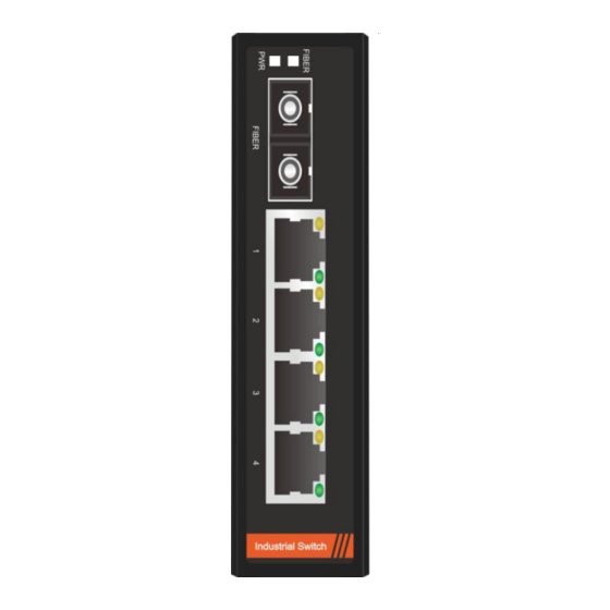
Overview Thanks for your purchasing. Please read the Quick Installation Guide for better user experience. Fiberroad 7 Series Industrial Ethernet Switch is environmentally hardened at standard operating temperature range -40 to 75°C for stable operation in harsh Industrial environment. The Industrial Switch is mini size, no fan, low power consumption, high reliability and stability, and easy to maintain. - Page 3 Panel Views of Industrial Switch Front Panel View 1. PWR: Power on LED 2. Fiber: Fiber LED 3. LK/ACT: Fiber link active 4. SYS: Switch working 5. Green LED: Gigabit port speed LED 6. Yellow LED: Current port link up 7.
- Page 4 Top Panel View 8. PWR1: Terminal block power input 1 9. PWR2: Terminal block power input 2 10. Grounding M3 screw 11. 5V DC: Input voltage DC5V 12. RS-232 serial console port 13. Reset - 4 -...
- Page 5 Rear Panel View 15. Wall mounting plate 16. DIN-Rail mounting kit 17. Wall mounting hole M3 screw 18. Metal spring 19. Aluminum case for heat dissipation - 5 -...
-
Page 6: Mounting Dimensions (Unit = Mm)
Mounting Dimensions (unit = mm) Small-size Industrial Switch - Unmanaged 2~5Ports Medium-size Industrial Switch - Managed 5~10Ports Big-size Industrial Switch - Managed 16~24Ports - 6 -... -
Page 7: Led Indicators
LED Indicators The front panel of the Industrial Switch contains several LED indicators. The function of each LED is described in the following table: Color State Description Power is being supplied to power input. Green Power is not being supplied to power input Fiber link active Fiber LK/ACT... -
Page 8: Wall Mounting
Wall Mounting You will find it convenient to mount Fiberroad Industrial Switch on the wall for some applications, as shown in the following figure: STEP 1 ☞ Remove the aluminum DIN-Rail plate from the rear panel of Industrial Switch, and then attach the wall mount plates with M3 screws as shown in the figure. -
Page 9: Wiring Requirements
Wiring Requirements WARNING Do not disconnect modules or wires unless power has been switched off or the area is known to be non-hazardous. The devices may only be connected to the supply voltage shown on the type plate. The devices are designed for operation with a Safety Extra-Low Voltage. -
Page 10: Grounding The Industrial Switch
Grounding the Industrial Switch Grounding and wire routing help limit the effects of noise due to electromagnetic interference. Run the ground connection from the ground screw to the grounding surface prior to connecting devices. ATTENTION This product is intended to be mounted to a well-grounded mounting surface such as a metal panel.
Need help?
Do you have a question about the 7 Series and is the answer not in the manual?
Questions and answers