Table of Contents
Advertisement
waltco.com
parts@waltco.com
Waltco Lift Corp.
Corporate Office United State
285 Northeast Ave.
Tallmadge, OH 44278
P: 330.633.9191
F: 330.633.1418
Generation 1 models have the Break-Away not Wrap Around Dock Bumper Plates
7/17/16
Tech Manual
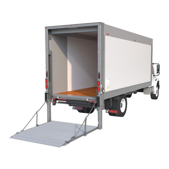
WDV & WDVBG
3500 - 6600 lb. Capacity Rail Liftgates
This manual covers:
Waltco Lift Corp.
United States
620 S Hambledon Ave.
City of Industry, CA 91744
P: 626.964.0990
F: 626.964.0149
WDV GEN 1 & GEN
See note in RED
1
Waltco Tech Support
800.633.9191
Phone:
2
Waltco Lift Inc.
Canada
90 North Queen St.
Etobicoke, ON M8Z 2C5
P: 888.343.4550
Advertisement
Table of Contents

Related Manuals for WALTCO WDV

Summary of Contents for WALTCO WDV
- Page 1 800.633.9191 Phone: parts@waltco.com Tech Manual WDV & WDVBG 3500 - 6600 lb. Capacity Rail Liftgates WDV GEN 1 & GEN This manual covers: See note in RED Waltco Lift Corp. Waltco Lift Corp. Waltco Lift Inc. Corporate Office United State...
-
Page 2: Table Of Contents
Table of Contents INTRODUCTION ............................3 LIFTGATE TERMINOLOGY ........................4-7 HYDRAULIC CIRCUIT DIAGRAM ......................8 POWER UNIT KEY COMPONENTS ......................9-14 ELECTRICAL & HYDRAULIC FLOW SCHEMATICS ................15-18 HYDRAULIC & ELECTRICAL SCHEMATICS BUILT FROM 4/09 THRU 10/11 ........19-20 HYDRAULIC & ELECTRICAL SCHEMATICS BUILT FROM 10/11 ............21-22 HYDRAULIC &... -
Page 3: Introduction
To ensure maximum performance of your Waltco liftgate, always specify and use “OEM Parts” from Waltco. This manual does not provide procedures for the servicing and repair of Waltco liftgates. Service and repair should only be performed by an authorized Waltco distributor. For information on the nearest authorized Waltco distributor contact: Waltco Lift Corp. -
Page 4: Liftgate Terminology
Liftgate Terminology 1. Street Side Upright 7. Chain Linkage Bar 13. Curb Side Runner 2. Curb Side Upright 8. Bottom Stop Catch 14. Control Switches 3. Lights 9. Main Deck 15. Closing Cylinder 4. Inside Switch 10. Deck Extension 16. Street Side Lift Cylinder 5. - Page 5 Liftgate Terminology 20. Control Switch 28. Charging Battery Cable 21. Light Wiring Harness 29. Grounding Battery Cable 22. Lights 30. Power Unit/Battery Box 23. Control Switch Extension Wires (Optional) 31. Box Cover 24. Inside Switch Extension Wires (Optional) 32. Master Disconnect 25.
- Page 6 Liftgate Terminology 35. Side Rail Assembly 38. Inner Guard Rail Assembly 36. Outer Guard Rail Assembly 39. Ramp Assembly 37. Guard Rail Latch Assembly 40. Gas Bottle Retention Chain WDVBG GR02366...
- Page 7 Liftgate Terminology EXPLANATION OF SPECIFICATION TAG MODEL No. DESCRIPTION CAPACITY WDVBG45 WDVBG-45 Series 4500 lb. WDV35 WDV-35 Series 3500 lb. WDV45 WDV-45 Series 4500 lb. WDV55 WDV-55 Series 5500 lb. WDV66 WDV-66 Series 6600 lb. MODEL NUMBER RATED CAPACITY Based on an evenly...
-
Page 8: Hydraulic Circuit Diagram
Series Hydraulic Circuit Diagram How the Series Hydraulics works Oil Flow in Back to Tank Series hydraulic circuit diagrams Oil is pumped into one cylinder, and the oil displaced from the other end feeds the second cylinder. When platform is at floor level, the oil bypasses to the tank and the Oil Flow Out... -
Page 9: Power Unit Key Components
Key Components For General 1 liftgates Call out of MTE Main & Auxiliary Power Unit Backup Switch 15 amp Auto Pressure Reset Switch gauge Motor Solenoid Motor Solenoid Backup Power Unit Motor selector switch Primary Power Unit RV4-Down 500 psi RV3-Open 1500 psi RV2-Up-Close... - Page 10 Key Components Call Out of Main & Auxiliary Power Unit Continued S3- Green A - Close 4W2P Lowering (Top Back) S1- Red 3W2P D - UP Selector POC (Bottom Back) C- Down S2- Brown 4W2P POC (Lower B- Open Front) S4- White (Lock Valve) Hydraulic Power Open Hydraulic...
- Page 11 Key Components All Generation 2 models will have the Bucher units Call out of Bucher Replacement Main & Auxiliary Power Unit Pressure 15 amp Auto 150 amp Backup Switch Tank gauge Reset Switch Circuit Breaker Ground Motor Solenoid Motor Solenoid Backup Power Unit Motor selector switch Primary Power Unit...
- Page 12 Key Components Call Out of Bucher Replacement Main & Auxiliary Power Unit Continued SV3- Green 4W2P Lowering (Top Back) C- Down SV1- Red 3W2P Selector POC D - UP (Bottom Back) SV2- Brown SV4- White 4W2P POC (Lock Valve) (Lower Front) B- Open A - Close...
- Page 13 Key Components Call out of Generation 2 Main & Auxiliary Power Unit with Divorced Manifold Tank Fill Cap Pressure Backup Switch gauge 15 amp Auto Reset Switch Fuse 150 amp Circuit Breaker Relays Primary Motor Solenoid Auxiliary Motor Solenoid Motor Thermal selector Switch...
- Page 14 Key Components Call Out of Generation 2 Main & Auxiliary Power Unit Continued SV4- White (Lock Valve) SV3- Green 4W2P Lowering (Front Left) Check Valve P- Pressure Line From Primary Pump. P1- Pressure Line From Aux. Pump. SV1- Red SV2- Brown 3W2P 4W2P POC Selector POC...
-
Page 15: Electrical & Hydraulic Flow Schematics
Electric / Hydraulic Flow Schematics S4 Valve/Coil activated for Up function Power Up... - Page 16 Electric / Hydraulic Flow Schematics S3 & S4 Valve/Coil activated for the Down Power Down function...
- Page 17 Electric / Hydraulic Flow Schematics Power Close S1 Valve/Coil activated for the Close function...
- Page 18 Electric / Hydraulic Flow Schematics S1 & S2 Valve/Coil activated for the Open function Power Open...
-
Page 19: Hydraulic & Electrical Schematics Built From 4/09 Thru 10/11
Electric / Hydraulic Schematics Built from 4/09 thru 10/11 Single pump Motor Single Relay... - Page 20 Electric / Hydraulic Schematics Built from 4/09 thru 10/11 Dual Pump Motor with Back Up/Auxiliary Single Relay...
-
Page 21: Hydraulic & Electrical Schematics Built From 10/11
Electric / Hydraulic Schematics Built from 10/11 Single Pump Motor Dual Relay... - Page 22 Electric / Hydraulic Schematics Built from 10/11 Dual Pump Motor with Backup/Auxiliary Dual Relay...
-
Page 23: Hydraulic & Electrical Schematic - Work Light
Work Light Electrical / Hydraulic Schematic... -
Page 24: Hydraulic & Electrical Schematics - Cycle Counter
Cycle Counter Schematics POWER UNIT HYDRAULIC/ELECTRICAL SCHEMATIC - SINGLE POWER UNIT – POWER DOWN REF 80101542 REV04... - Page 25 Cycle Counter Schematics POWER UNIT HYDRAULIC/ELECTRICAL SCHEMATIC - DUAL PUMP MOTOR WITH BACKUP/AUXILLARY – POWER DOWN REF 80101542 REV04...
-
Page 26: Hydraulic & Electrical Schematic- Gravity Down On Demand
Gravity Down On Demand Schematics POWER UNIT HYDRAULIC/ELECTRICAL SCHEMATIC - SINGLE POWER UNIT – GRAVITY DOWN ON DEMAND REF 80101585 REV04... - Page 27 Gravity Down On Demand Schematics POWER UNIT HYDRAULIC/ELECTRICAL SCHEMATIC - DUAL PUMP MOTOR WITH BACKUP/AUXILLARY – GRAVITY DOWN ON DEMAND REF 80101582 REV04...
-
Page 32: Troubleshooting Guide
Troubleshooting Guide CHECKING THE OIL LEVEL IN THE RESERVOIR Check the oil with the platform fully raised and in the open position. Oil should be within 3” below the top of the reservoir. The liftgate is shipped with Shell Tellus 15. Check the owner’s manual for additional recommended oils. Fill as required with the specified fluid in the owner’s manual. - Page 33 Troubleshooting Guide PLATFORM DOES NOT RAISE OR RAISES SLOW- MOTOR RUNS • Check and inspect the oil level in the reservoir. Check the fluid viscosity. See Checking the oil level in the reservoir • Check the battery(s) for full state of charge. Replace any batteries that cannot be fully charged.
- Page 34 Troubleshooting Guide PLATFORM WILL NOT LIFT TO FULL CAPACITY • Check the fluid in the reservoir, fill with correct fluid. See Checking the oil level in the reservoir • Check for any mechanical obstructions or any mechanical damage. Look for any broken or bent parts that could interfere with normal operation. •...
- Page 35 Troubleshooting Guide PLATFORM WILL NOT OPEN OR CLOSE *To open press open and up, to close press close and up. IF MOTOR DOES NOT RUN: SEE MOTOR DOES NOT RUN • Check voltage on (S1 & S2 for power open function / S1 only for power close function) valves while the controls are activated.
- Page 36 Troubleshooting Guide PLATFORM LEAKS DOWN Run platform to the top and hold the button for 30 seconds to bleed the system through before determining if there is any leakage. Does only one side leak down? • If Yes: Replace cylinder on that one side where it is leaking. •...
-
Page 37: Lift Cylinder Replacement Instruction
Supplement to WDV Cylinder Replacement Instructions for Passengers Side Cylinder Only When replacing the passengers side cylinder on an WDV liftgate please note there is a pressure compensating flow control valve located at the top of the passengers side cylinder. - Page 38 Lift Cylinder Replacement Lift Cylinder Replacement Instructions Replace: 1. Lower platform to the ground. 2. Remove lower cylinder pin on both cylinders. 3. Run liftgate up until both cylinders are fully retracted. (Approx. 20 seconds) 4. Disconnect both hoses from top of defective cylinder. 5.
-
Page 39: Closing Cylinder Bleeding Procedure
Closing Cylinder Bleeding Procedure 1. Open Platform. 2. Lower Platform to 10” above the ground. 3. Remove pin retainer from lower closing cylinder pin. 4. Remove lower closing cylinder pin from Cylinder and platform clevis. 5. Fully retract closing cylinder using switch. 6. -
Page 40: Hydraulic Oil Changing Procedure
Hydraulic Oil Changing Procedure 1. Position liftgate platform open and on the ground. 2. Remove oil from tank: • SPX dual power units remove the drain plug on the bottom of the tank and drain. • All other units siphon oil from tank. 3. -
Page 41: High Pitch Noise Repair
High Pitch Noise Repair A high pitch squealing noise can be cause by the following: 1: Tight cylinder seal. Noise happens in both raising and lowering. Use Caterpillar additive 1U-9891. Start with 2 ounces, engage up switch to bypass, Hold for 30 seconds then cycle liftgate 4-5 times or until noise stops. Add about two ounces more at a time, until noise stops. -
Page 42: Replacing Switch And Power Close Hoses
Replacing Switch and Power Close Hoses 1. Lower the platform in the open position to the ground and cut power to the liftgate. Unbolt the switch from the runner. 2. Remove the hose cover by removing the 2 bolts and cutting the 3 wire ties that hold the switch wire in place. - Page 43 Replacing Switch and Power Close Hoses 6. Secure the hoses to the front cover leaving 8” and 16” of hose exposed from the edge of the lower guard. 8” from edge of guard for hose 75489469 16” from edge of female end.
-
Page 44: Travel Latch Engagment
Travel Latch Engagement CHECK TRAVEL LATCH ENGAGEMENT Store platform in travel latch. Check that travel ear engages the cam by 3/8” minimum. If travel ear engages cam less than 3/8” add retaining ring to drivers side hinge pin between platform and runner hinge tube. -
Page 45: Preventive Maintenance
Quarterly Preventive Maintenance Waltco recommends that the WDV / WDVBG liftgate be inspected at 6 month or 3000 cycle intervals to help assure proper function and operation of the liftgate. Note: Photocopy the following PM Checklist to help keep track of periodic maintenance on the liftgate. Keep completed form with maintenance records. - Page 46 Quarterly Preventive Maintenance Inspect Hydraulic and Electrical Components Corrected 18 Inspect for hydraulic leaks on cylinders, hoses and fittings OK Repair Needed Inspect hoses for fraying or cracking (especially where hoses enter or exit OK Repair Needed Corrected 19 the housing cover and hose extension cover). Inspect that closing hoses are tracking properly and secured to liftgate OK ...
-
Page 47: How To Order Parts
When ordering repair or replacement parts, please include all the information asked for below. If this information is not available, a complete written description or sketch of the required part will help WALTCO identify and deliver the needed part to you. - Page 48 Notes...
Need help?
Do you have a question about the WDV and is the answer not in the manual?
Questions and answers