Advertisement
Quick Links
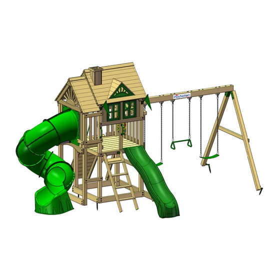
Rock Wall and Ladder
positions are interchangeable.
Calypso Deluxe
Model: 304
(BOXES: 301N-1, 301N-2, 320,
Extreme Tube Slide II box, Slide
Box with 308 piece inside)
Copyright © 2019 PlayNation Play Systems
All Rights Reserved
*52-2106-W*
166 Etowah Industrial Court
Canton, GA 30114
www.playnation.com
52-2106-W
Advertisement

Related Manuals for PlayNation Play Systems Calypso Deluxe 304


Summary of Contents for PlayNation Play Systems Calypso Deluxe 304
- Page 1 Calypso Deluxe Model: 304 (BOXES: 301N-1, 301N-2, 320, Extreme Tube Slide II box, Slide Box with 308 piece inside) Copyright © 2019 PlayNation Play Systems All Rights Reserved *52-2106-W* 166 Etowah Industrial Court Canton, GA 30114 www.playnation.com...
- Page 2 Please inspect and inventory all parts immediately upon accepting delivery. Use the inventory pages in the manual to make sure you have received all necessary parts. The quickest method to get any parts that are missing or damaged is use our “Quick Response Center”...
- Page 3 PLAYNATION WARRANTY 2019 PlayNation Play Systems warrants its Regal™, Horizon™ and Empire™ series swing sets to be free from defects in workmanship and materials, under normal use and conditions, for the lifetime of the product for above ground structural wood components and for two years for the following accessories (e.g., swings, hardware, plastics, tarps, rope ladder, etc.).
- Page 4 PlayNation’s discretion, may be accomplished by submitting photographs or by delivery of the defective part to PlayNation: PlayNation Play Systems; 190 Etowah Industrial Ct.; Canton, GA 30114. Any warranty claim must include proof of purchase, including the date of purchase.
- Page 5 IMPORTANT SAFETY GUIDELINES This product is recommended for use by children ages 3-11. This product is intended for residential use only and not intended for use in any public setting. A safety surface such as mulch or recycled tire should be used under the play set to prevent injury from falls. Also a 6 foot safety zone should be used around the entire play set.
- Page 6 THIS PAGE INTENTIONALLY LEFT BLANK...
- Page 7 PRODUCT REGISTRATION - CALYPSO DELUXE - PlayNation manufactures the ™ 3 EASY WAYS TO REGISTER finest quality products that are designed for outstanding Complete the online registration form at: OPTION 1 strength and durability. We back http://www.playnation.com/register our products with an unparalleled warranty.
- Page 8 THIS PAGE INTENTIONALLY LEFT BLANK...
- Page 9 IMPORTANT – PLEASE READ Congratulations! You have just purchase one of the finest residential wooden swing sets available today. As with any wooden product that spends its entire life outside, in varying elements, it is important to know what to expect with your new swing set so that your family can enjoy it for many years.
- Page 10 WARNING: Children must NOT use this play set until it has been completely assembled and inspected by an adult to ensure it has been properly installed PlayNation Play Systems 166 Etowah Industrial Court Canton, GA. 30114...
- Page 11 Rock Wall and Ladder positions are interchangeable. Model: 304 (BOXES: 301-1, 301-2, 304, 320, Extreme Tube Slide II Box, Slide Box with 308 piece inside) REV: 1.24.2019...
- Page 12 TABLE OF CONTENTS Safety Guidelines………………………………………..……......Pages 3-6 Leveling Fort, General Information and Definitions..........Pages 7-9 How to Install T-nuts, Board Identification, Predrill Lag screw Directions and Swing Beam Loading…………………………………........Pages 10-14 Site Plan, Safety Zones, Required Tool List and Kit Contents....... Pages 14-15 Hardware, Lumber and Accessory Checklists........…..Pages 18-36 Corner Post Layout and Adding T-Nuts to Corner Posts...……..………...…..
- Page 13 Safety and Maintenance Tips for Your New Play Set: NOTE: Your children’s safety is our #1 concern. Observing the following statements and warnings reduces the likelihood of serious or fatal injury. Please review these safety rules regularly with your children. •...
- Page 14 Safety and Maintenance Tips for Your New Play Set: (continued) Playgrounds should be inspected on a regular basis. If any of the following conditions are noted, they should be removed, corrected, or repaired immediately to prevent injuries. • Hardware that is loose, worn or that has protrusions or projections. •...
- Page 15 PLAYGROUND SURFACING MATERIALS SECTION 4 OF THE CONSUMER PRODUCT SAFETY COMMISSION’S OUTDOOR HOME PLAYGROUND SAFETY HANDBOOK Select Protective Surfacing One of the most important things you can do to reduce the likelihood of serious head injuries is to install shock-absorbing protective surfacing under and around your play equipment.
- Page 16 Play Set Surfacing Recommendations: Below are some of the recommendations that the U.S. Consumer Product Safety Commission (CPSC) offers from its Handbook for Public Playground Safety. The guide can be downloaded in full at www.cpsc.gov/PageFiles/122149/325.pdf 1. Protective Surfacing - Since almost 60% of all injuries are caused by falls to the ground, protective surfacing under and around all playground equipment is the most critical safety factor on playgrounds.
- Page 17 2. Fall Zones - A fall zone, covered with a protective surfacing material, is essential under and around equipment where a child might fall. This area should be free of other equipment and obstacles onto which a child might fall. Stationary climbing equipment and slides should have a fall zone extending a Minimum of 6’...
- Page 18 General Info to Review Before Installation • Depending on your experience, assembly of the playset can take as little as 6 hours up to 24 hours, depending on size, after inventory of parts; therefore, we recommend you set aside a full two days for assembly. •...
- Page 19 This page is a list of definitions and explanations used throughout our instructions to aid you in the assembly of your play set. Offset Holes- Throughout the installation procedures we will refer to parts with offset holes. This refers to the orientation of the holes on the board. An offset hole is one that is closer to one side than it is the other or in other words, it is not centered on the board.
- Page 20 Common Installation Practice Installing T-nuts When installing T-nuts into the wood, use a smooth faced hammer to set the face of the T-nut flush into the wood. Corner Post T-nut Insert the barrel of the T-nut into the predrilled hole. Using a smooth faced hammer, drive the T-nut until the face of the T-nut is flush to the wood.
- Page 21 HOW A T-NUT WORKS THE FIRST STEP IN OUR ASSEMBLY INSTRUCTIONS IS TO INSERT T-NUTS INTO THE CORNER POSTS. A T-NUT IS A FASTENER WHICH IS THREADED ON THE INSIDE AND IT FUNCTIONS JUST LIKE A STANDARD HEX NUT. YOU INSERT THE T-NUTS INTO THE PREDRILLED HOLES IN THE CORNER POSTS.
- Page 22 BOARD IDENTIFICATION 1. On the end of each board there should be a small white tag that is stapled or stuck into place. Remove the staples and/or tag after the board is installed. 2. This white identifcation tag displays the thickness, width, length and an abbreviated description of the part.
- Page 23 PRE-DRILL LAG SCREW DIRECTIONS Pre-drilling holes for lag screws will make it easier to drive the screws in by hand. "Jobber" length drill bits are available in sizes that are longer than standard drill bits and those are ideal for the job. When using the drill bit you will have to "spot" drill the post and then remove the board you are attaching to finish drilling the hole.
- Page 24 SWING BEAM LOADING Weight Limits for Accessories: The weight limit for a Swing Belt is 225 lbs. (Although 150lbs is the maximum recommended swinging weight capacity for the swing position.) The weight limit for a Trapeze Bar is 125 lbs. Maximum Allowable swinging weight for a three position swing: 1) The maximum allowable swinging weight at each Swing Belt position is 150 lbs.
- Page 25 Swing Beam Height: 7'-2-3/4" Height: 10'-4-1/2" 1st Level 47-3/8" sq. x 48-1/4"H Please familiarize yourself with the manual, parts/components and general 2nd Level 19-3/8" x 47-3/8" x 58-1/4"H construction process of your new playset before getting started. SITE PLAN: 18'-6" 3'-11 8 "...
- Page 26 SAFETY ZONES 30'-3 2 " 6'-0" 13'-9 8 " 6'-0" 27'-11 16 " 6'-0" 6'-0" 6'-0" 6'-0" 13'-9 " 6'-0" 6'-0"...
- Page 27 REQUIRED TOOL LIST: ___ Standard or Cordless Drill w/ Phillips Bit (#2 square bit provided) ___ Drill Bits 3/32”, 1/8”, 3/8”, 7/64”, 9/64”, 11/64” and a 1” Paddle style bit. ___ ½” Wrench and Socket ___ ½” Deep Well Socket ___ 9/16”...
- Page 28 11-0020 #14 X 1-1/4" 301/301D Hardware PAN HEAD PAGE 1 OF 2 SCREW REV: B 9/16/2015 JH QTY: 6 #8 X 1-1/4" WOOD SCREW QTY: 8 #8 X 1-1/2" WOOD SCREW QTY: 106 #8 X 2" WOOD SCREW QTY: 191 #8 X 2-1/2"...
- Page 29 11-0020 301/301D Hardware PAGE 2 OF 2 REV: B 9/16/2015 JH 3/8 X 3-1/2" 5/16" X 3-1/2" HEX LAG HEX LAG SCREW SCREW QTY: 12 QTY: 26 #2 SQUARE DRILL BIT QTY: 1 PLASTIC BOLT CAP QTY: 19 3/8 x 9" 3/8 x 7"...
- Page 30 11-0092 304 Hardware PAGE 1 OF 1 REV: B 1/17/2019 JH #8 X 1-1/4" WOOD SCREW QTY: 4 #8 X 1-1/2" WOOD SCREW QTY: 72 #8 X 2" WOOD SCREW QTY: 72 #8 X 2-1/2" WOOD SCREW 3/8" X 1-1/8" QTY: 6 BLACK PLASTIC PLUG...
- Page 31 PICTURE DESCRIPTION QTY. 1 X 5 X 52" ROOF FINISHER (TONGUE ONLY) 1-5-5200-RF 1 X 5 X 52" ROOF STARTER (GROOVE ONLY) 1-5-5200-RS 1 X 5 X 52" ROOF BOARD (TONGUE AND GROOVE) 1-5-5200-RB 3-1/2 X 3-1/2 X 52" ROOF PEAK 1-6-5200-RP NOTE: 2 X 4 X 12"...
- Page 32 PICTURE DESCRIPTION QTY. 2 X 4 X 17" LADDER STEP 2-4-1700-LS 2 X 4 X 35-1/2" ROOF SUPPORT - LEFT 2-4-3550-RSL 2 X 4 X 35-1/2" ROOF SUPPORT - RIGHT 2-4-3550-RSR 2 X 4 X 43-3/4" SUN SUPPORT 2-4-4375-SS 2 X 4 X 47-3/8" FACE BOARD 2-4-4738-FB 2 X 4 X 47-3/8"...
- Page 33 PICTURE DESCRIPTION QTY. 2 X 4 X 47-3/8" STRINGER 2-4-4738-S 2 X 4 X 48" FORT SUPPORT 2-4-4800-FS 2 X 4 X 57" LADDER LEFT SIDE 2-4-5700-LLS 2 X 4 X 57" LADDER RIGHT SIDE 2-4-5700-LRS 2 X 4 X 57" ROCK WALL SIDE 2-4-5700-RWS...
- Page 34 PICTURE DESCRIPTION QTY. 2 X 6 X 47-3/8" ARCHED SIDE TOP BOARD 2-6-4738-ASTB 2 X 6 X 47-3/8" END SANDBOX BOARD 2-6-4738-ESB 2 X 6 X 86" REAR SANDBOX BOARD 2-6-8600-RSB 4 X 4 X 47-3/8" SWING BEAM MOUNT 4-4-4738-SBM 4 X 4 X 96"...
- Page 35 PICTURE DESCRIPTION QTY. 4 X 6 X 108" SWING BEAM 4-6-10800-SB 5/4 X 2 X 13" SMALL RAY 125-2-1300-SR 5/4 X 2 X 17" LARGE RAY 125-2-1700-LR 5/4 X 2-1/4 X 11- 1/2" HORIZONTAL WINDOW SUPPORT 125-225-1150- 5/4 X 3 X 28" PANEL SLAT 125-3-2800-PS NOTE:...
- Page 36 PICTURE DESCRIPTION QTY. 5/4 X 4 X 40-1/2" DECK SPACER 125-4-4050-DS 5/4 X 6 X 10-1/2" ROOF PEAK SUPPORT 125-6-1050-RPS 5/4 X 5 X 23-7/8" BOTTOM ROCK WALL BOARD 125-5-2388-BRWB 5/4 X 5 X 23-7/8" ROCK WALL BOARD 125-5-2388-RWB 5/4 X 6 X 20" VERTICAL WINDOW SUPPORT...
- Page 37 PICTURE DESCRIPTION QTY. 1 X 5 X 18-3/8" ROOF BOARD 1-5-1838-RB 1 X 5 X 18-3/8" ROOF FINISHER 1-5-1838-RF 1 X 5 X 18-3/8" ROOF STARTER 1-5-1838-RS 1 X 6 X 17" ROOF PEAK 1-6-1700-RP 5/4 X 3 X 32" EXTREME PANEL SLAT 125-3-3200-EPS 5/4 X 4 X 40-1/2"...
- Page 38 PICTURE DESCRIPTION QTY. 5/4 X 6 X 47-3/8" DECK BOARD 125-6-4738-DB 2 X 4 X 11" EXTREME BOTTOM PANEL BOARD 2-4-1100-EBPB 2 X 4 X 16" CENTER DECK SUPPORT 2-4-1600-CDS 2 X 4 X 19-3/8" PANEL/DECK SUPPORT 2-4-1938-PDS 2 X 4 X 27-1/2" CENTER POST 2-4-2750-CP 2 X 4 X 35-1/2"...
- Page 39 PICTURE DESCRIPTION QTY. 2 X 4 X 47-3/8" EXTREME TOP PANEL BOARD 2-4-4738-ETPB 2 X 4 X 47-3/8" WINDOW TOP PANEL BOARD 2-4-4738-WTPB 2 X 6 X 47-3/8" SANDBOX BOARD 2-6-4738-SB 4 X 4 X 32" EXTREME SLIDE POST 4-4-3200-ESP 4 X 4 X 37-3/4"...
- Page 40 PICTURE DESCRIPTION QTY. WAVE SLIDE 03-0016-G PLASTIC DORMER SUNBURST 07-0031 SWING W/CHAINS 04-0002 TRAPEZE W/CHAINS 04-0006...
- Page 41 PICTURE DESCRIPTION QTY. SWING PLATE 11-5002 CLIMBING ROCKS (07-0008 IS A PACK OF ROCKS A-FRAME SWING BRACKET 11-5010 11-0020 HARDWARE BOXES: 301 & 304 11-0092...
- Page 42 PICTURE DESCRIPTION QTY. IRON DUCTILE SWING HANGERS 11-4012 GREEN BRACKET 11-5013 SPRING CLIP 11-4003...
- Page 43 PICTURE DESCRIPTION QTY. 10' ROPE (GREEN) DORMERS AND CHIMNEY (UNASSEMBLED) 320 BOX FLAG KIT 09-1014 GROUND STAKE (PAIR) 07-0016-P...
- Page 44 PICTURE DESCRIPTION QTY. NOTE: ACTUAL PRODUCT MAY VARY TELESCOPE 07-0037-G NOTE: ACTUAL PRODUCT MAY VARY STEERING WHEEL 07-0004 SAFETY HANDLES (PAIR) 07-0005...
- Page 45 PICTURE DESCRIPTION QTY. WINDOW 07-0013 CROWN 07-0019 TIC TAC TOE (UNASSEMBLED) 07-0010 MANUFACTURER (NOT SHOWN) LOGO PLATE...
- Page 46 PICTURE DESCRIPTION QTY. SAFETY WARNING PLATE 11-5023 EXTREME TUBE SLIDE II 03-0020...
- Page 47 STEP 1: CORNER POST LAYOUT 1: This step is critical to building the fort properly. If any mistakes are made here, you will need to dis-assemble and then re-assemble to make your corrections. 2: Lay out each of the 4 x 4 x 96” Corner Posts in the area you intend on building the fort side of the playset.
- Page 48 STEP 2: INSERTING T-NUTS INTO CORNER POSTS 1: Use a hammer to seat the t-nuts after inserting them into the holes shown in the diagram below. 2: The barrel of the t-nut should go in the hole first. Hammer the t-nut until it is flush/almost flush to the corner posts.
- Page 49 STEP 3: SANDBOX BOARDS AND PANEL SUPPORTS 1: The 2 x 4 x 47-3/8” Panel Supports (offset holes up) attach to the front and rear corner posts with two 5/16” x 4-1/2” hex bolts and two 5/16” washers. 2: Attach the top holes in the 2 x 6 x 47-3/8” End Sandbox Boards (offset holes up) to the front and rear corner posts with two 5/16”...
- Page 50 STEP 4: REAR SANDBOX/PANEL SUPPORT BOARD 1: The 2 x 4 x 47-3/8” Panel Support (offset holes down) attaches to the side of the Right Corner Posts with two 5/16” x 4-1/2” hex bolts and two 5/16” washers. 2: The 2 x 6 x 86” Right Sandbox Board (offset holes down) attaches to the side of the Right Corner Posts with two 5/16”...
- Page 51 STEP 5: DECK SUPPORTS 1: Attach one Deck Support (offset holes down) to the inside of the Left and Right Corner Posts with two 5/16” x 4-1/2” hex bolts and 5/16” washers. Note: One Panel Support Board was removed for clarity. 2 X 4 X 47-3/8"...
- Page 52 STEP 6: LEVELING THE PLAY SET AND INSTALLING LAG SCREWS 1: Level your play set frame. Level side to side and front to back. Check the diagonals for square. Once you have a level and square play set frame you may install lag screws. 2: Install one 5/16”...
- Page 53 STEP 7: FORT SUPPORTS 1: Place a 5/16” Tee Nut into the hole in the Fort Supports as shown. 2: From the inside of the Right Panel Board loosely attach each Fort Support with one 5/16” x 2-1/2” Hex Bolt and one 5/16” washer. 3: Measure 2”...
- Page 54 STEP 8: DECK SPACERS 1: Place a 5/4 x 4 x 40-1/2” Deck Spacer between the Left and Right Corner Posts on top of the Deck Supports as shown below. 2: The Deck Spacer side should be flush with the inside of the Panel Support. 3: Attach each Deck Spacer to the Deck Supports with two 2”...
- Page 55 STEP 9: PANEL SUPPORT BOARD 1: Place the 2 x 4 x 47-3/8” Panel Support against the front side of the play set with offset holes up. Attach the Panel Support with two 5/16” x 4-1/2” hex bolts and 5/16” washers. 2: Center the 2 x 4 x 27-1/2"...
- Page 56 STEP 9A: DECK STRINGER 1: Center the 2 x 4 x 47-3/8" Deck Stringer underneath the Deck Spacers. 2: Attach the Deck Stringer to the Deck Spacers with two #8 x 2" wood screws. 2 x 4 x 47-3/8" Deck Stringer #8 x 2"...
- Page 57 STEP 10: FACE BOARDS 1: Locate two 2 x 4 x 47-3/8” Face Boards. 2: Attach a Face Board to the front of the Left Corner posts making sure the top side is flush with the top side of the Panel Supports. 3: Attach the Face Board with six 2-1/2”...
- Page 58 STEP 11: LADDER ASSEMBLY 1: Lay one 2 x 4 x 57” Ladder Side on a flat surface with channels facing down. Place the barrel of a T-Nut in the hole at the top of the Ladder Side, and secure with a hammer. Repeat this step for the other Ladder Side.
- Page 59 DECISION FOR LADDER AND ROCK WALL At this point in the instructions you must decide how your playset will be built. If you wish you may place the ladder on the front or the rear of the playset. Likewise you may place the rock wall on the front or the rear of the playset.
- Page 60 STEP 12: ATTACHING THE LADDER ON FRONT NOTE: IF YOU ARE INSTALLING THE LADDER ON THE REAR OF THE PLAYSET PROCEED TO STEP 12A NOW. 1: The Ladder attaches to the front of the play set, 24-3/8" from the outside edge of the Front- Right corner post.
- Page 61 STEP 12A: ATTACHING THE LADDER ON REAR 1: The Ladder attaches to the rear of the play set, 14-7/16" from the outside edge of the Left-Rear corner post. 2: Make sure the ladder is level. The bottom edge of the 90 brackets should be 3/4” up from the bottom edge of the 2 x 4.
- Page 62 STEP 13: ROCK WALL 1: Locate two 2 x 4 x 57 Rock Wall Side boards. Lay the boards out as shown and insert a 5/16” t-nut into the hole on the inside of each board. Use a hammer to set each t-nut flush with the board.
- Page 63 STEP 14: ROCK WALL 1. Locate ten 5/4 x 5 x 23-7/8” Rock Wall Boards and one 5/4 x 5 x 23-7/8” Bottom Rock Wall Board with one big hole in it. 2. Place one Rock Wall Board at the top of the Rock Wall Sides nearest the holes where you previously installed the tee nuts.
- Page 64 STEP 15: ROCK WALL 1: Locate two 90 Green Brackets, two 5/16” washers and two 5/16” x 1-1/2” hex bolts. 2: Fasten the tapered side of each 90 Green Bracket to each Rock Wall Side with a 5/16” x 1-1/2” hex bolt and 5/16” washer. ** IF THE ROCK WALL IS BEING INSTALLED ON THE REAR THEN FASTEN THE BRACKETS AS SHOWN.
- Page 65 STEP 16: ROCK WALL 1: Locate two bags of Climbing Rocks. Inside each bag should be five rocks, fifteen #14 x 1- 1/4” pan head screws and fifteen 1/4” flat washers. 2: Place the Climbing Rocks in a staggered pattern on the Rock Wall Boards. Place one rock on each board except for the bottom rock wall board with the hole in it.
- Page 66 STEP 17: ROCK WALL 1: Place the 5/4 x 3 x 23-7/8” Rock Wall Top Cap on top of the Rock Wall Sides flush with the top Rock Wall Board. 2: Fasten the 5/4 x 3 x 23-7/8” Rock Wall Top Cap to the Rock Wall Sides and the top Rock Wall Board with four 2”...
- Page 67 STEP 18: ATTACHING ROCK WALL ON REAR NOTE: IF YOU ARE ATTACHING THE ROCK WALL ON THE FRONT OF THE PLAYSET PROCEED TO STEP 18A NOW. 1: The Rock Wall attaches to the rear of the play set, 11-3/4” from the outside edge of the rear corner post.
- Page 68 STEP 18A: ATTACHING ROCK WALL ON FRONT 1: Place the 4 x 4 x 21-1/16" Rock Wall Mount 2" away from the side of the left front corner post. The top of the mount should be flush to the top of the deck. 2: Fasten the Rock Wall Mount to the panel support with six #8 x 3"...
- Page 69 STEP 19: DECK BOARDS 1: Seven 5/4 x 6 x 47 3/8” Deck Boards will lay across the Deck Supports, flush to the Face Boards. There will be approximately a 1/4” gap between each Deck Board. 2: Space the Deck Boards evenly across the supports. 3: Secure each Deck Board to the Deck Supports and the Deck Stringer with five 2”...
- Page 70 STEP 20: ANGLE SUPPORTS 1: Four 2 x 4 x 13” Angle Supports are mounted underneath the deck on the left and right of the fort. (These are called out by the letter “X”) 2: Attach each Angle Support (X) to the Deck Support with two 2-1/2” wood screws at the top going through the Deck Support first and then into the Angle Support (X).
- Page 71 STEP 21: PANEL AND PANEL SUPPORT BOARDS **NOTE: IF YOU ARE BUILDING THE PLAYSET WITH THE ROCK WALL ON THE FRONT THEN PROCEED TO STEP 21A.** 1: Place the 2 x 4 x 12” Bottom Panel Board - Left and 2 x 4 x 12” Bottom Panel Board - Right on top of the 2 x 4 as shown below with offset holes up.
- Page 72 STEP 21A: ARCHED TOP AND PANEL SUPPORT BOARDS 1: Place one Arched Side Top Board on the rear of the set where shown. Attach the Arched Side Top Board through the top holes with 5/16" x 4-1/2" hex bolts with washers. Then attach the bottom holes with 5/16"...
- Page 73 STEP 22: PANEL SUPPORT 1: Place the 2 x 4 x 47-3/8” Panel Support on top of the 2 x 4 at the right side of the play set with offset holes down. Attach the Panel Support with two 5/16” x 3-1/2” lag screws and two 5/16”...
- Page 74 STEP 23: PANEL SLATS 1: Locate eleven 5/4 x 3 x 28” Panel Slats. Four Panel Slats will be installed at rear of the play set. Seven Panel Slats will be installed at the right of the play set. 2: At the right of the play set center one Panel Slat over the center of each deck board. Square each Panel Slat to the Panel Support.
- Page 75 STEP 24: SWING BEAM SUPPORT 1. The 4 x 4 x 47-3/8” Swing Beam Support has counter-sunk holes in the center and on the ends. Install the Swing Beam Support so that the counter-sunk holes on each end of the beam face out, and the counter-sunk holes in the center face down.
- Page 76 STEP 25: SWING BEAM PLATE 1: Place the Swing Beam Plate on top of the Swing Beam Support, lining up the pilot holes. 2: Fasten the Swing Beam Plate to the Swing Beam Support on the outside holes using 3/8” x 3-1/2”...
- Page 77 STEP 26: ATTACH SWING LEGS TO BRACKET 1: Place the 4 x 4 x 96” Swing Legs flush to the top of the Swing Leg Bracket. 2: Predrill 11/64" pilot holes into the Swing Legs through the holes in the Swing Leg Bracket. 3: Fasten the Swing Legs to the Swing Leg Bracket with eight 3/8”...
- Page 78 STEP 27: IRON DUCTILE SWING HANGERS 1: Line up the holes of the Iron Ductile Swing Hangers with the holes in the Swing Beam. 2: Fasten the Iron Ductile Swing Hangers to the Swing Beam using 3/8” x 7” carriage bolts with torque washers on top of the Swing Beam, and 3/8”...
- Page 79 STEP 28: REST SWING BEAM ON FORT *Two people are required for this step. 1. Sit the swing beam legs upright. 2. Line up the pre-drilled holes and rest the swing beam on top of the fort and swing legs. Make sure the iron ductiles are facing down.
- Page 80 STEP 29: SWING BEAM TO SWING LEGS 1: Fasten the Swing Beam to the Swing Leg Bracket using 3/8” x 6-1/2” carriage bolts with torque washers on top of the Swing Beam, and 3/8” lock nuts with 3/8” washers underneath. 2: Predrill an 11/64"...
- Page 81 STEP 30: SWING BEAM TO FORT *An extra person is required for this step. 1: Have one person line up the hole in the end of the Swing Beam with the middle hole on the Swing Beam plate. The other person may have to carry the other end where the legs are located to accomplish this task.
- Page 82 STEP 31: LEVEL THE SWING BEAM 1: Place a level on top of the Swing Beam and adjust the legs in or out as needed to make the Swing Beam level.
- Page 83 STEP 32: SWING LEG CROSS-MEMBER 1: Position the 2 x 4 x 58” Swing Leg Cross-Member against the Swing Legs. 2: Level the Swing Leg Cross-Member and mark through the holes onto the swing legs. 3: Drill 11/64" holes by 2" deep at each mark. 4: Secure the Cross-Member to the Swing Legs with 3/8”...
- Page 84 STEP 33: ARCHED TOP BOARDS 1: Place one Arched Side Top Board on the rear side of the play set at the top. Attach the Arched Side Top Board through the top hole into the t-nut in the corner post with 5/16” x 4-1/2” hex bolts and 5/16”...
- Page 85 STEP 34: DECK SUPPORTS 1: Measure 9" up from the deck onto the left rear corner post. Make the top of the Deck Support flush to the mark. 2: Make the end of the Deck Support flush to the inside of the corner post. 3: Mark through the hole onto the corner post.
- Page 86 STEP 35: CORNER POSTS 1: Hammer a T-Nut into the hole at 55" in the 4 x 4 x 90" Corner Post. 2: Fasten the Deck Support to the Corner Post with a 5/16" x 4-1/2" hex bolt and a 5/16" washer.
- Page 87 STEP 36: PANEL SUPPORTS 1: Hammer three 5/16" T-nuts into the holes on the inside of each of the 4 x 4 x 90" Corner Posts. 2: Place a 2 x 4 x 19-3/8" Panel Support (OFFSET UP) at the top, middle and lower positions on the outside of the corner posts.
- Page 88 STEP 37: SIDE TOP WINDOW BOARD AND SANDBOX BOARD NOTE: IF YOU ARE BUILDING THE PLAYSET WITH THE LADDER ON THE REAR OF THE SET THEN GO TO STEP 37A NOW. 1: Hammer four T-nuts into the inside of the 90" corner posts to attach the boards shown. 2: Fasten the 2 x 6 x 47-3/8"...
- Page 89 STEP 37A: ROCK WALL SIDE TOP PANEL BOARD AND SANDBOX BOARD. 1: Hammer four T-nuts into the inside of the 90" corner posts to attach the boards shown. 2: Fasten the 2 x 4 x 47-3/8" Rock Wall Side Top Panel Board (OFFSET UP) to the middle of the 90"...
- Page 90 STEP 38: DECK SPACERS AND DECK BOARDS 1: Place the 5/4 x 4 x 40-1/2" Deck Spacers between the 96" posts and the 90" posts. 2: Place the 5/4 x 6 x 47-3/8" Deck Boards between the Deck Spacers. 3: Space the Deck Spacers and Deck Boards about 3/8" apart. You may use a 3/8" bolt between boards to space them out.
- Page 91 STEP 39: EXTREME TOP PANEL BOARD 1: Install a T-nut in the top hole on the inside of each of the 90" corner posts. 2: Install a T-nut in the 2ND hole from the top on the outside of each of the 90" corner posts.
- Page 92 STEP 40: EXTREME SLIDE POSTS 1: Hammer a T-nut into the hole at the top of each 4 x 4 x 32" Extreme Slide Post. 2: Place each post on top of the deck spacer and fasten them to the top panel board with a 5/16"...
- Page 93 STEP 41: EXTREME BLOCK 1: Place the 4 x 4 x 37-3/4" Extreme Block under the deck spacer. The outside face of the block should be flush to the outside of the extreme posts. 2: Fasten the Block to the deck spacer through the center hole with a #8 x 2" wood screw. Now go back and add 4 more #8 x 2"...
- Page 94 STEP 42: CENTER DECK SUPPORT 1: Place the 2 x 4 x 16" Center Deck Support under the deck as shown. Center it side to side. 2: Fasten the Center Deck Support to the deck boards and deck spacer with #8 x 2" wood screws.
- Page 95 STEP 43: PANEL SLATS 1: Place two 5/4 x 3 x 28" Panel Slats against the top and bottom boards on the inside as shown. 2: Use the measurements shown to locate the slats. Then secure each slat at the top and bottom with a #8 x 2"...
- Page 96 STEP 44: STEP 1: Place the 2 x 4 x 47-3/8" Deck/Panel Support Board (OFFSET UP) against the 96" corner posts on the inside. Space the board so the bottom is 3-1/4" off the deck. 2; Fasten the Deck/Panel Support Board to the corner posts with 5/16" x 3-1/2" lag screws with 5/16"...
- Page 97 STEP 45: ROOF SUPPORTS 1: Drill a 1/8" pilot hole about 1-1/2" from the end of one of the Roof Supports. 2: Place the Roof Supports together and line them up at the tip. Then install a #8 x 2- 1/2"...
- Page 98 STEP 46: ROOF SUPPORTS 1: Place the Roof Support assembly on the 96" posts as shown below. Push DOWN on each Roof Support before you tighten the bolt. 2: Fasten each Roof Support to the corner post with a 5/16" x 4-1/2" Hex Bolt and a 5/16" washer.
- Page 99 STEP 47: ROOF SUPPORT ASSEMBLY 1: Place the Roof Supports together as shown. Fasten the Roof Peak Support to the Roof Supports with #8 x 2" wood screws. 2: Next you will use a Roof Starter on each side of the Roof Support Assembly as a spacer. You will temporarily fasten the starters here to place the Roof Support Assembly onto the posts correctly in the next step.
- Page 100 STEP 48: ROOF SUPPORTS 1: Place the Roof Support Assembly directly underneath the previous installed Roof Support Assembly. 2: The boards used as spacers should be flush to the bottom of the UPPER Roof Supports. 3: Fasten the Roof Support Assembly to the corner posts with 5/16" x 3-1/2" lag screws and 5/16"...
- Page 101 STEP 49: REMOVAL OF PARTS These parts must be removed to install the Roof on the upper platform. 1: Remove the upper Roof Support Assembly and set aside for later. 2: Remove the Roof Starters from the lower Roof Support Assembly. Roof Support Assembly (Upper) Roof Support Assembly (Lower)
- Page 102 STEP 50: ROOF SUPPORT ASSEMBLY 1: Place the Roof Supports together as shown below. 2: Fasten the Roof Peak Support to the Roof Supports with #8 x 2" Wood Screws. 5/4 x 6 x 10-1/2" Roof Peak Support 2 x 4 x 35-1/2" 2 x 4 x 35-1/2"...
- Page 103 STEP 51: ROOF SUPPORT ASSEMBLY INSTALLATION 1: Place the Roof Support Assembly on the outside of the 90" corner posts with the triangle facing out. 2: Fasten the Roof Support Assembly to the corner posts with 5/16" x 4-1/2" hex bolts and 5/16"...
- Page 104 STEP 52: ROOF STARTERS 1: Place the 1 x 5 x 18-3/8" Roof Starters at the peak of the roof as shown. The edges should touch one another but the parts should not overlap. 2: Before installing the starters check the dimensions shown below to make the roof supports parallel.
- Page 105 STEP 53: ROOF PEAK 1: Place the 1 x 6 x 17" Roof Peak on top of the Roof Starters. Line up the end of the Roof Peak with the end of the Starters as shown so that they are flush to one another. 2: Fasten the Roof Peak to the Roof Starters with #8 x 1-1/4"...
- Page 106 STEP 54: ROOF BOARDS 1: Place a 1 x 5 x 18-3/8" Roof Board on top of the roof supports. Place the tongue of the roof board into the groove of the roof starter. Make the ends of the boards flush. 2: Fasten the Roof Board to the roof supports with #8 x 1-1/2"...
- Page 107 STEP 55: ROOF FINISHERS 1: Place the tongue of a 1 x 5 x 18-3/8" Roof Finisher into the groove of the Roof Board above it. Make the ends of the boards flush. 2: Fasten the Roof Finisher to the roof supports with #8 x 1-1/2" wood screws. 3: Repeat substeps 1-2 to install the second Roof Finisher on the other side of the roof.
- Page 108 STEP 56: ROOF SUPPORTS 1: Replace the Roof Support assembly that was removed in Step 49. Fasten it to the corner posts with 5/16" x 4-1/2" hex bolts and 5/16" washers. 2: Take the second Roof Support Assembly that was made in Step 50 and install it over the Swing Beam Mount.
- Page 109 STEP 57: ROOF STARTERS 1: Place the 1 x 5 x 52" (groove only) Roof Starter boards at the peak of the roof. Measure at the bottom of the roof supports. In this case for example the measurement is 47-3/8". After you install the Roof Starters the dimension at the top should be 47-3/8"...
- Page 110 STEP 58: ROOF PEAK 1: Place the 3-1/2 x 3-1/2 x 52" Roof Peak on top of the Roof Starter Boards and fasten with four #8 x 1-1/2" wood screws. 3-1/2 x 3-1/2 x 52" Roof Peak #8 x 1-1/2" Wood Screw...
- Page 111 STEP 59: ROOF BOARDS/ROOF FINISHERS AND CHIMNEY AND DORMERS 1: Place the 1 x 5 x 52” Roof Boards on top of the Roof Supports, fitting the tongue into the groove of the Roof Starter. The holes in the Roof Boards should be centered over the Roof Supports.
- Page 112 STEP 60: SUN SUPPORT AND SUN 1: Place a 2 x 6 x 16" Sun centered on top of the 2 x 4 x 43-3/4" Sun Support. The face of the Sun should be flush with the face of the Sun Support. Fasten the Sun to the Sun Support with two #8 x 3 wood screws.
- Page 113 STEP 61: SUN RAYS 1: All the sun ray pieces get installed to the inside surface of the Roof Supports and the Sun piece. 2: Place the 5/4 x 2 x 17” Large Ray centered under the peak of the Roof Supports. Attach the Large Ray to the Roof Support and Sun with two #8 x 1-1/2”...
- Page 114 STEP 62: SUN SUPPORT, SUN AND EXTREME PANEL SLATS 1: Place the 2 x 6 x 16" Sun on top of the 2 x 4 x 43-3/4" Sun Support. The face of the Sun should be flush with the face of the Sun Support. Fasten the Sun to the Sun Support with two #8 x 3"...
- Page 115 STEP 63: SUN SUPPORT ASSEMBLY 1: Place the Sun Support assembly from the prior step under the roof supports as shown. The panel slats will be on the inside. 2: Level the Sun Support and then fasten it to the Sun Support with #8 x 2-1/2" wood screws.
- Page 116 STEP 64: SUN RAYS 1: All the sun ray pieces get installed to the inside surface of the Roof Supports and the Sun piece. 2: Place the 5/4 x 2 x 17” Large Ray centered under the peak of the Roof Supports. Attach the Large Ray to the Roof Support and Sun with two #8 x 1-1/2”...
- Page 117 STEP 65: WINDOWS 1: Center the 5/4 x 6 x 20" Vertical Window Support 5/16" above the center post beside the ladder or rock wall at the front of the playset. Fasten it at the top and bottom with #8 x 2" wood screws. 2: Place a window on top of the 2 x 4 at the front of the set.
- Page 118 STEP 66: WINDOWS 1: Place the Windows in the openings as shown. The 1" tall portion of the window frame should be at the top as described previously. Fasten the Window on the sides with #8 x 1-1/2" wood screws. Windows #8 X 1-1/2"...
- Page 119 STEP 67: SAFETY BOARD 1: Place the 2 x 4 x 47-3/8" Panel and Deck Support (Safety Board) offset down 24" above the bottom of the long sandbox board. This board is meant to be a visual aid to keep children from running through the base of the playset into the swing zone. 2: Fasten the Panel and Deck Support (Safety Board) to the corner posts with 5/16"...
- Page 120 STEP 68: WAVE SLIDE 1: Place the Wave Slide centered in the opening at the front of the playset. 2: Place the rear edge of the slide about 4-1/2" in from the board on the front of the playset. 3: Fasten the slide to the deck using #14 X 1-1/4" pan head screws. HINT: You may use a 1/8"...
- Page 121 STEP 69: ROCK WALL ROPE NOTE: IF YOU ARE INSTALLING THE ROCK WALL ON THE FRONT OF THE PLAYSET THEN PROCEED TO STEP 69A. 1: Thread the Rope as shown in the diagram below. Tie a FIGURE 8 knot behind this hole Add up to 2 Thumb knots to aid in climbing.
- Page 122 STEP 69A: ROCK WALL ROPE 1: Use a 1" spade drill bit to drill a hole through the 2 x 4 x 47-3/8" Panel Support 12-9/16" from the left end centered vertically on the board. TIP: drill through the board until the tip of the bit just pokes through the other side.
- Page 123 STEP 69A: ROCK WALL ROPE (CONTINUED) 1: Thread the Rope as shown in the diagram below. Tie a FIGURE 8 knot behind this hole. Add up to 2 Thumb knots to aid in climbing. FRONT OF PLAYSET Tie Thumb knots behind this hole until all of the rope is used.
- Page 124 STEP 70: TELESCOPE 1: Mount Telescope as shown. DETAIL A Telescope 2" wood screw provided with Telescope Telescope Base allowed to pivot. Snap the ends of the base into the sockets on the side of the Telescope. NOTE; IF YOU ARE MOUNTING THE LADDER ON THE REAR OF THE PLAYSET REAR OF PLAYSET YOU WILL SEE A LADDER HERE.
- Page 125 STEP 71: CROWN 1: Place the Crown on top of the sun wood piece above the swing beam mount. 2: Attach the Crown to the sun with two #8 X 1-1/2" wood screws. Crown #8 X 1-1/2" Wood Screws...
- Page 126 STEP 72: FLAG KIT 1: Place the Flags on the front of the play set centered on the corner posts. 2: Attach the plastic base of each Flag to the corner post with the 1/2" phillips head screws provided with the Flags. Flag Flag...
- Page 127 STEP 73: TIC TAC TOE 1: Assemble the Tic Tac Toe panel according to the instructions in the box. IGNORE Step 6 and Step 7 in the instructions. 2: Attach the two 1-3/8" x 1-5/8" x 10-1/2" L Tic Tac Toe boards to the green plastic brackets with the 1"L phillips pan head screws provided in the Tic Tac Toe box.
- Page 128 STEP 74: SAFETY HANDLES 1: Fasten the Safety Handles with the hardware that is included with the Safety Handles. 2: Fasten the Safety Handles above the Rock Wall and Ladder as shown below. Safety Handles THERE WILL BE A LADDER HERE IF REAR OF PLAYSET YOU CHOSE TO PUT IT ON THE Safety Handles...
- Page 129 STEP 75: STEERING WHEEL 1: Place the Steering Wheel insert inside the Steering Wheel. 2: Use the 2-1/2" lag screw and washer to fasten the Steering Wheel to the end of the swing beam. Do not over-tighten the lag screw or the Steering Wheel will not turn. 3: Place the Steering Wheel Cap over the center of the Steering wheel and snap it into the Steering Wheel Insert.
- Page 130 STEP 76: SWINGS 1: Hang the Swing Belts and the Trapeze as shown. Adjust the swings up or down by clipping the swing chains onto higher or lower chain links. Trapeze Swing Belt Swing Belt Swing Hanger Spring Clip Swing Chain DETAIL A...
- Page 131 STEP 77: GROUND STAKES 1: Hammer a Ground Stake into the earth next to each swing leg at an angle. Do not hold the upper portion of the stake after the first couple of hits or it may vibrate harshly against your hand.
- Page 132 STEP 78: SAFETY HANDLES - UPPER LEVEL 1: Place the Safety Handles at the appropriate height for your child centered on the inside of the middle corner posts. 2: Fasten each Safety Handle to the post with #14 x 1-1/4" pan head screws and 1/4" washers that are included with the handle.
- Page 133 STEP 79: PLUGS 1: Install black plastic plugs at each end of the holes shown below. 8 plugs required. Plug...
- Page 134 STEP 80: TUBE SLIDE 1: Build the Tube Slide according to steps 1 through 9 in the instruction manual included with the slide. 2: Rest the bottom of the slide entry upon the arched board or rock wall side top panel board.
- Page 135 STEP 81: BOTTOM PANEL BOARD 1: Hammer a t-nut into the hole in the corner post as shown. 2: Fasten the 2 x 4 x 11" Extreme Bottom Panel Board to the corner post with a 5/16" x 4- 1/2" hex bolt and a 5/16" washer. 3: Level the board and install a 5/16"...
- Page 136 STEP 82: SLATS 1: Fasten the Panel Slat on either side of the slide with a #8 x 2" wood screw. Panel Slat #8 x 2" Wood Screw...
- Page 137 STEP 83: LOGO PLATE 1: Place the manufacturer logo plate centered onto the front of the swing beam. 2: Fasten the logo plate with two 2" wood screws. Logo Plate - Secure with 2" Wood Screws.
- Page 138 304 Playset Leftover Parts List Note: Due to the 300 series playsets being modular there will be some leftover parts when the playset is completed. There may also be leftover hardware pieces at the end. This is normal and should not be cause for concern.
- Page 139 APPENDIX...
- Page 140 Chimney and Dormers Hardware Kit 8/10/2015 JH #8 X 2-1/2" WOOD SCREW QTY: 2 #8 X 2" WOOD SCREW QTY: 4 #8 X 1-1/2" WOOD SCREW QTY: 14 #8 X 1-1/4 WOOD SCREW QTY: 6 #2 SQUARE DRIVE BIT QTY: 1 USE THE RULER TO THE RIGHT TO MEASURE YOUR BOLTS AND SCREWS.
- Page 141 PICTURE DESCRIPTION QTY. CHIMNEY LEFT SIDE ASSEMBLY CHIMNEY RIGHT SIDE ASSEMBLY CHIMNEY FRONT ASSEMBLY...
- Page 142 PICTURE DESCRIPTION QTY. CHIMNEY REAR ASSEMBLY 5/4X3X6-3/4" CHIMNEY MOUNTING BLOCK DORMER LEFT SIDE ASSEMBLY...
- Page 143 PICTURE DESCRIPTION QTY. PLASTIC DORMER SUNBURST (07-0031) DORMER RIGHT SIDE ASSEMBLY...
- Page 144 STEP 1: DORMER 1: OVERLAP THE LEFT DORMER SIDE ONTO THE PEAK SUPPORT OF THE RIGHT DORMER SIDE. 2: MAKE SURE THE FRONT ROOF EDGES ARE FLUSH TO ONE ANOTHER 3: FASTEN THE LEFT DORMER SIDE TO THE PEAK SUPPORT WITH #8 X 1-1/2" WOOD SCREWS. REPEAT SUBSTEPS 1-3 TO CONSTRUCT ANOTHER ROOF ASSEMBLY.
- Page 145 STEP 2: DORMER 1: PLACE THE PLASTIC DORMER SUNBURST AGAINST THE FRONT FACE SUPPORT ON THE LEFT AND RIGHT ROOF SIDES. 2: PREDRILL 7/64" PILOT HOLES BY 1/2" DEEP INTO THE ROOF SIDES AT EACH HOLE LOCATION. 3: INSTALL #8 X 1/2" PAN HEAD SCREWS TO FASTEN THE SUNBURST TO THE ROOF SIDES. REPEAT SUBSTEPS 1 THROUGH 3 TO CONSTRUCT THE SECOND DORMER.
- Page 146 STEP 3: DORMER 1: PLACE THE DORMER ASSEMBLY ON THE ROOF AS SHOWN. 2: FOR 1500 SERIES UNITS LINE UP THE BOTTOM EDGE OF THE PLASTIC SUNBURST WITH THE LOWER EDGE OF THE 8TH ROOF BOARD. 3: CENTER THE DORMER FROM SIDE TO SIDE ON TOP OF THE ROOF. 4: ATTACH THE DORMER TO THE ROOF WITH ONE #8 X 2-1/2"...
- Page 147 STEP 4: CHIMNEY 1: FIND THE FRONT AND LEFT SIDE OF THE CHIMNEY. 2: ATTACH THE FRONT AND LEFT SIDES OF THE CHIMNEY WITH A 2" WOOD SCREW. USE A 2" WOOD SCREW IN THIS LOCATION CHIMNEY FRONT CHIMNEY LEFT SIDE 1: FIND THE REAR AND RIGHT SIDE OF THE CHIMNEY.
- Page 148 STEP 5: CHIMNEY 1: ATTACH THE CHIMNEY SIDES FROM THE PREVIOUS SIDES TO FORM THE CHIMNEY WITH 2" AND 1-1/4" WOOD SCREWS. USE A 2" WOOD SCREW IN THIS LOCATION (EACH SIDE) USE 1-1/4" WOOD SCREWS IN THIS LOCATION (EACH SIDE)
- Page 149 STEP 6: CHIMNEY 1: FASTEN THE 5/4 X 3 X 6-3/4" CHIMNEY MOUNTING BLOCK TO THE ROOF WITH #8 X 1-1/2" WOOD SCREWS. YOU CAN PLACE THE BLOCK AT ANY DESIRED PLACE ON THE ROOF. USE THE DIAGRAM BELOW AS A GUIDE FOR A SUGGESTED PLACE TO MOUNT THE CHIMNEY. 2: AFTER INSTALLING THE CHIMNEY MOUNTING BLOCK PLACE THE CHIMNEY ASSEMBLY ON THE ROOF SO THAT THE INSIDE OF THE BACK WALL RESTS AGAINST THE BLOCK.
Need help?
Do you have a question about the Calypso Deluxe 304 and is the answer not in the manual?
Questions and answers