
Subscribe to Our Youtube Channel
Related Manuals for Tamarack Solar STP-LCR-R Series


Summary of Contents for Tamarack Solar STP-LCR-R Series
- Page 1 STP-LCR-R Series Installation Manual STP-8212-MAN 2018 Edition v1.0 For models: STP-LCR/82R STP-LCR/120R...
-
Page 2: Table Of Contents
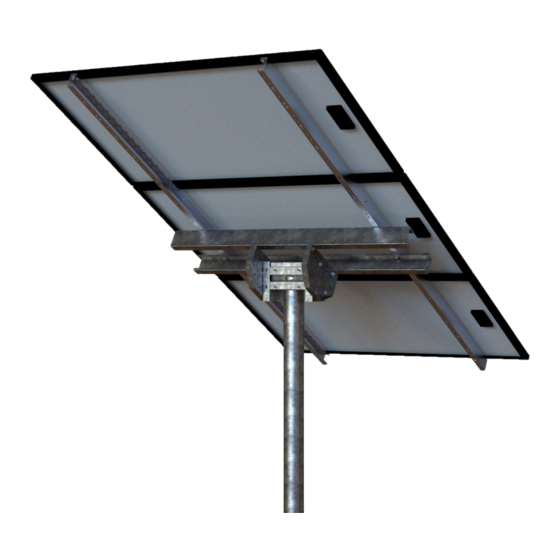
Pole Mount can support installations in a wide range of locations. Customer Support Tamarack Solar makes every effort to ensure your m ounting kit is easy to install. If you need assistance at any point in your installation or have suggestions on how we can improve your experience, call customer support at 1-800-819-7236 or email us at info@tamaracksolar.com... - Page 3 STP-LCR-R Series Galvanized coated sheet steel components will show rust on cut edges and is normal and will not affect the structure and function of the mount. STP-LCR/82R ITEM PART NUMBER DESCRIPTION QTY. 51-04PC-012 REV A 4" Pipe Clamp Half...
-
Page 4: Pre Assembly For Model Stp-Lcr/120
STP-LCR-R Series Pre Assembly for Model STP-LCR/120 Step 1: Connecting Panel Support Channels A. Lay two 60” panel support channels end to end with a connector in the middle. B. Using a connector, bolt the 60” panel support channels together. Tighten the 5/16-18 x 7/8”... -
Page 5: Step 5: Attach Cross Rails To Tilt Plates
STP-LCR-R Series Step 5: Attach Cross Rails to Tilt Plates. Attach cross rails to the tilt plates, open sides facing IN, with 3/8-16 x 1.” bolts, locks and flats, nuts. Cross rails are to be on center across the tilt plates and parallel to each other, Torque to 240 in-lbs (Detail F) (dry). - Page 6 STP-LCR-R Series Detail D Detail C Helpful tip: pre install - 3/8" bolt for ease of assembly in Detail E Detail E...
- Page 7 STP-LCR-R Series Detail F STP-LCR/82R Detail F STP-LCR/120R Detail G Detail H STP-LCR/82R SHOWN...
-
Page 8: Foundation Hole Guidelines
STP-LCR-R Series Foundation Hole Guidelines (see charts pages 9,10 The suggestions below are recommendations only. It is the installer’s responsibility to validate foundation parameters prior to installation, as local geotechnical report may be required to assess ground conditions. We recommend consulting with a local engineer familiar with local regulations and build site requirements, including soil conditions, terrain and load criteria (wind, snow, seismic). - Page 9 STP-LCR-R Series...
- Page 10 STP-LCR-R Series Footing Chart 2 panel STP-LCR/82R 60 and 72 cell modules 60 and 72 cell modules Design Wind Speed (V) Ground Snow Load (p 0° TILT ASCE 7-10 20 30 40 50 ASCE 7-05 110 MPH 72 72 60...
- Page 11 STP-LCR-R Series Footing Chart 2 panel STP-LCR/120R 60 and 72 cell modules 60 and 72 cell modules Design Wind Speed (V) Ground Snow Load (p 0° TILT ASCE 7-10 20 30 40 50 ASCE 7-05 110 MPH 72 60 Soil Type...
-
Page 12: Installer Responsibility
Tamarack Solar by Purchaser, any employee of Purchaser, client of Purchaser, end-user of the Product or other party, even if Tamarack Solar has been advised of the possibility of such claims or demands (collectively, “Third Party Claims”). This limitation applies to all materials provided by Tamarack Solar during...
Need help?
Do you have a question about the STP-LCR-R Series and is the answer not in the manual?
Questions and answers