
Subscribe to Our Youtube Channel
Related Manuals for Tamarack Solar Ground Mount Kit


Summary of Contents for Tamarack Solar Ground Mount Kit
- Page 1 Tamarack Solar Solar Products Tamarack Ground Mount Kit Installation Manual 2021 TAMARACK SOLAR - REVISION 5 FM SYSTEM MANUAL...
-
Page 2: Table Of Contents
Limited Warranty Customer Support Tamarack Solar makes every effort to ensure your mounting kit is easy to install. If you need assistance at any point in your installation or have suggestions on how we can improve your experience, call customer support at 1-800-819-7236 ext 556 or email us at support@tamaracksolar com Technical Support: 707-234-8107 or www.support@tamaracksolar.com... -
Page 3: Features And Ratings
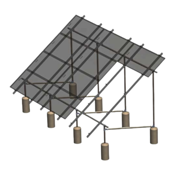
Built-in wire management for module and microinverter cables Tamarack Product Summary The Tamarack Solar Ground Mount system is a visually appealing photovoltaic (PV) module installation system that significantly lowers PV module installation cost by allowing the installation professional to stock fewer parts and to complete the installation in less time. -
Page 4: Installer Responsibilities
• We recommend consulting with your local building department about local regulations and building require- ments, including soil conditions, terrain, and wind and snow load requirements. Local conditions and • Use only Tamarack Solar Products parts or parts approved by Tamarack; substituting parts may void any applicable warranty. -
Page 5: System Components
Tamarack Ground Mount System Components 3.1 inch Rail Rail Splice Pipe Mount Clamp Socket Tee Flexible Tee MLPE Adapter Ground Lug 5050 Clamp Module Frame Ground Lug Wire Management Clip Rail End Cap 2021 TAMARACK SOLAR - REVISION 5 FM SYSTEM MANUAL... -
Page 6: Tools Required And Torque Specifications
Exposure Category B is an urban, suburban or wooded area. Obstructions the size of single family dwellings must surround the structure at within 2,630 ft or 10 times the mounting structure height in all directions, whichever is greater. 2021 TAMARACK SOLAR - REVISION 5 FM SYSTEM MANUAL... -
Page 7: Installation Preparation
3 Modules per Column 4 Modules per Column Front Vertical Rear Vertical Front Vertical Rear Vertical Slope Pipe (inches) Pipe (inches) Pipe (inches) Pipe (inches) (deg) Above Ground Above Ground Above Ground Above Ground 2021 TAMARACK SOLAR - REVISION 5 FM SYSTEM MANUAL... -
Page 8: Vertical Post Spacing
Where L = Module Length in inches and N = Number of Columns in the array being installed. The horizontal pipe will cantilever past the end posts and should extend past the end posts an equal distance on each end. 2021 TAMARACK SOLAR - REVISION 5 FM SYSTEM MANUAL... -
Page 9: Foundation Design And Construction
Re-install the layout strings to make sure that the holes are excavated at the proper locations and adjust the hole centers if necessary. Clean out as much loose soil as you can from the augured holes. 2021 TAMARACK SOLAR - REVISION 5 FM SYSTEM MANUAL... - Page 10 Minimum Foundation Depth (inches) - 3 Modules per Column Minimum Foundation Depth (inches) - 3 Modules per Column Tamarack Ground Mount Kit Foundation Info Wind Speed Rating Soil Braced/ Slope Type Unbraced (deg) 2021 TAMARACK SOLAR - REVISION 5 FM SYSTEM MANUAL...
- Page 11 Minimum Foundation Depth (inches) - 4 Modules per Column Minimum Foundation Depth (inches) - 4 Modules per Column Tamarack Ground Mount Kit Foundation Info Wind Speed Rating Soil Braced/ Slope Type Unbraced (deg) 2021 TAMARACK SOLAR - REVISION 5 FM SYSTEM MANUAL...
- Page 12 Fine adjustment to level can also be done using shims between the beam pipes and the X-Braces. If the horizontal beams are long, you can do this in sections for easier handling. Check for array tilt consistency along the entire length of array and adjust if necessary. 2021 TAMARACK SOLAR - REVISION 5 FM SYSTEM MANUAL...
- Page 13 2021 TAMARACK SOLAR - REVISION 5 FM SYSTEM MANUAL...
- Page 14 Angle the brace pipe up toward the Flex Tee on the south post. After loosening the set screws on this Flex Tee, guide the end of the pipe into the socket and lower the Flex Socket Tee assembly down until the pipe end is 2021 TAMARACK SOLAR - REVISION 5 FM SYSTEM MANUAL...
- Page 15 Repeat this whole process for installing the cross braces on each north/south pair of posts. There may need to be changes to the lengths of the brace pipes from location to location, especially if the installation site is not completely level. 2021 TAMARACK SOLAR - REVISION 5 FM SYSTEM MANUAL...
-
Page 16: Attaching Rails
Clamp flange nuts in order to slide the rail up or down for alignment. Tighten the U-bolt nuts to 72 inch-pounds (6 foot-pounds) and the flange nuts 144 inch-pounds (12 foot-pounds) on all rail assemblies. 2021 TAMARACK SOLAR - REVISION 5 FM SYSTEM MANUAL... -
Page 17: System Grounding
The Socket Tees provide a grounding path between all connected sections of pipe. Because all of the elements of an entire unified ground mount array are bonded electrically, the Tamarack Solar Ground Mount only requires a single Ground Lug for the grounding connection. -
Page 18: Module Level Power Electronics (Mlpe) Installation And Wire Management
To center the column of modules on the rails, take that measurement of extra rail length and divide by 2. In the example above, that would be 5.25 inches of rail that would extend past the bottom module and past top module in the column. 2021 TAMARACK SOLAR - REVISION 5 FM SYSTEM MANUAL... -
Page 19: Module Compatability
Back View Module Compatability The solar modules listed on the next two pages have been certified to meet UL 2703 standards when installed with a Tamarack Solar FM Rail System. 2021 TAMARACK SOLAR - REVISION 5 FM SYSTEM MANUAL... - Page 20 (40mm), LR6-60 PE (40mm), LR6-72 PE (45mm), LR6-60 BK (40mm Black frame), LR6-72 BK (40mm Black LONGi frame), LR6-60 PB (40mm Black frame), LR6-72 PB (45mm Black frame) Number in paranthesis signifies frame profile height. 2021 TAMARACK SOLAR - REVISION 5 FM SYSTEM MANUAL...
- Page 21 Certified Power Optimizer List for UL2703 Listing Program Manufacturer Model Numbers P400J, P600, P700, P730, P800p, P800s SolarEdge Enphase M250-72, 250-60, M215-60, C250-72, S230, S280, IQ 6, IQ 6+, IQ 7, IQ 7+, IQ 7X, Q Aggregator 2021 TAMARACK SOLAR - REVISION 5 FM SYSTEM MANUAL...
-
Page 22: Limited Warranty
Manufacturers Limited Product Warranty Tamarack Solar Products (“Manufacturer”), the manufacturer of the Tamarack Solar FM solar mounting system (the “Product”), warrants to the end-user of the Product (“buyer”), that while installed as part of the original solar electric system (the “System”) at the original installation site, the Product shall be free from defects in materials and workmanship for a period of twenty-five (25) years (the “Limited Product Warranty”),... - Page 23 2021 TAMARACK SOLAR - REVISION 5 FM SYSTEM MANUAL...
Need help?
Do you have a question about the Ground Mount Kit and is the answer not in the manual?
Questions and answers