Table of Contents
Advertisement
Quick Links
CONTENTS
SAFETY INFORMATION...........................
SYMBOL EXPLANATION .........................
SAFETY PRECAUTIONS..........................
MAINTENANCE......................................
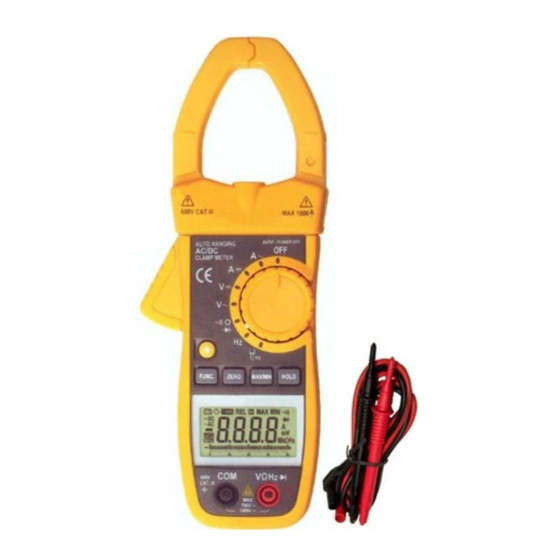
GENERAL DESCRIPTION........................
PANEL DESCRIPTION.............................
FORWARD LAYOUT................................
OPERATING INSTRUCTIONS...................
SPECIFICATIONS...................................
AUTO POWER OFF................................
REPLACING THE BATTERY.....................
ACCESSORIES......................................
PAGE
1
2
2
4
4
5
8
9
14
18
18
19
SAFETY INFORMATION
The digital clamp meter has been designed
according to IEC1010 − 1 and IEC1010 − 2 − 032
concerning safety requirements for electrical
measuring instruments and hand-held current
clamps with double insulation overvoltage category
1000V CAT II 600V CAT III and pollution 2.
This meter complies with the requirements of the
following European Community Directives:
89 / 336 / EEC (Electromagnetic Compatibility) and
73 / 23 / EEC (Low Voltage) as amended by 93 /
68 / EEC (CE Marking).
However, electrical noise or intense electromag-
netic fields in the vicinity of the equipment may
disturb the measurement circuit.
Measuring instruments will also respond to
unwanted signals that may be present within the
measurement circuit.
Users should exercise care and take appropriate
precautions to avoid misleading readings.
− 1 −
Advertisement
Table of Contents

Related Manuals for Morris Products 57262


Summary of Contents for Morris Products 57262
-
Page 1: Table Of Contents
SAFETY INFORMATION CONTENTS PAGE The digital clamp meter has been designed according to IEC1010 − 1 and IEC1010 − 2 − 032 concerning safety requirements for electrical SAFETY INFORMATION……………………... measuring instruments and hand-held current SYMBOL EXPLANATION ……………………. clamps with double insulation overvoltage category SAFETY PRECAUTIONS…………………….. -
Page 2: Symbol Explanation
any sign of damage or abnormality before SYMBOL EXPLANATION every use. If any abnormal conditions exist Important safety information, refer to the (i.e. broken test leads, cracked cases, operating manual. display not reading, etc.), do not attempt to Dangerous voltage may be present. take any measurements. -
Page 3: Maintenance
In addition, there is a radius lamp near the clamp, MAINTENANCE It is lit along with measuring current. ● Never touch exposed wiring, connections or any live circuit when attempting to take PANEL DESCRIPTION measurements. Transformer jaws ● Before opening the case, always disconnect Pick up DC or AC current flowing through test leads from all energized circuits. - Page 4 LCD display In the Relative mode, the value shown on the LCD is always the difference between the stored reference value and the present reading. If the new reading is the same as the reference value, the display will be zero. FUNC.
-
Page 5: Forward Layout
FORWARD LAYOUT OPERATING INSTRUCTIONS DC VOLTAGE MEASUREMENT 1. Insert the black and red test leads into the COM and VΩHz input terminals respectively. 2. Set rotary switch at desired V position. Connect the test lead tips in parallel with the circuit to be measured. - Page 6 NOTE: DC CURRENT MEASUREMENT Set the rotary switch at A position. 1. Make certain that all test leads are discon- Press ZERO button to enter the zero mode . nected from the meter terminals. Press the trigger to open transformer jaw 2.
- Page 7 the circuit under test has all power removed FREQUENCY MEASUREMENT and that all capacitors have been discharged Insert the black and red test leads into the fully. COM and VΩHz input terminals respectively. Set the rotary switch to Hz position. CONTINUITY TESTING Connect the test leads across the source or Insert the black and red test leads into the...
-
Page 8: Specifications
NOTE: Weight: Approx. 330g ℃ ℃ Frequency range: 40Hz to 400Hz ( > 20A ). Operating: to 35 Storage temperature: −10 ℃ ℃ to 50 SPECIFICATIONS DC VOLTAGE Accuracy: ±% of reading ±number of least significant digits at Accuracy Range Resolution ℃... - Page 9 Overload Protection: DC CURRENT 250V dc or rms, ac for all ranges Range Resolution Accuracy 400A 0.1A ±(3.0%of rdg +5 digits) FREQUENCY 600A Range Resolution Accuracy ±(3.0%of rdg +5 digits) 1000A 40Hz Overload Protection: 400Hz 120% ranges for 60 seconds max ±(0.1%of rdg +1digit)...
-
Page 10: Auto Power Off
AUTO POWER OFF and remove the test leads from the input terminals. To extend the battery life, Auto Power Off function Remove screws on the battery cover and is provided. If no key operations of range changing open the cover. occurs in about 30 minutes, the meter will be Remove the exhausted battery and replace turned off automatically. - Page 11 OPERATOR’S 57262 INSTRUCTION MANUAL ACA/DCA CLAMP METER...
Need help?
Do you have a question about the 57262 and is the answer not in the manual?
Questions and answers