Table of Contents
Advertisement
Quick Links
Advertisement
Table of Contents

Related Manuals for Morris Products 57276


Summary of Contents for Morris Products 57276
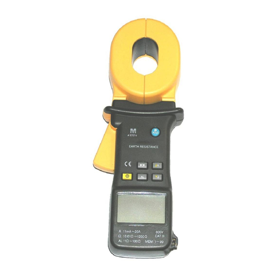
- Page 1 Model 57276 EARTH RESISTANCE CLAMP USERS MANUAL...
-
Page 2: Table Of Contents
CONTENTS WARNING - - - - - - - - - - - - - - - - - - - - - - - - - - - - - - - - - - - - - - - - - - - - - - 1 MAINTENANCE - - - - - - - - - - - - - - - - - - - - - - - - - - - - - - - - - - - - - - - - - 1 INTRODUCTION - - - - - - - - - - - - - - - - - - - - - - - - - - - - - - - - - - - - - - - - - 2... -
Page 3: Warning
WARNING * Before measuring, note that the metal objects or the conductors that connect with the electric equipment are dangerous, as well as the earth system. So when you test the electric equipment, you must especially pay attention to safety. * The warning letter that is in the back of your instrument reminds you of the values that must not be exceeded, the measurement ranges, and briefly, the operation of the clamp. -
Page 4: Introduction
INTRODUCTION Modern industrial electronic equipment is in quick development. A good Earth ground is becoming an efficient system to prevent from interference and thunderbolt. A safe and quick earth tester is most needed. The Earth resistance clamp is a breakthrough from traditional testers. Neither the supplementary earth leads nor the break earth equipment is necessary. -
Page 5: Summary Of Function
SUMMARY OF FUNCTION FUNCTION BUTTON ON/OFF/EXIT SET MODE ▲A A MEASUREMENT/ ALARM VALUE INCREASE/ RECORD NUMBER SELECT Ω MEASUREMENT/ ALARM VALUE MINISH / ▼Ω RECORD NUMBER SELECT HOLD DISPLAY HOLD SELECT ALARM MODE SELECT /SET MEMORY MODE SWITCH BUZZER ON/OFF +Ω... -
Page 6: Lcd Display
EARTH RESISTANCE 1mA 20A 600V CAT II : 0.01 1200 AL : 1 LCD DISPLAY (Note: when switch is on, the clamp performs a rapid auto-test of the whole display. All the symbols on the LCD are displayed for this short time.) ―... - Page 7 1. Buzzer ON symbol 2. HOLD symbol : holds the last measurement 3. Interference Symbol: shows that the current in the loop is disturbed such that the resistance measurement value is not guaranteed. 4. Clamp symbol: shows that the clamp is closed incorrectly, cannot measure. 5....
- Page 8 12. High Alarm symbol 13. Low Alarm symbol 14. Alarm mode symbol 15. Low voltage indication symbol 16. Auto Power Off symbol 17. Record number symbol 18. Read memory mode symbol 19. save in memory mode symbol 20. 4 digit LCD digital display OPERATION 一、ON/OFF OPERATION button switches ON/OFF.
- Page 9 二、EARTH RESISTANCE MEASUREMENT 1. After switching on, the instrument is automatically in measurement current mode, you can press the ▼ Ω button to configure for resistance measurement mode. 2. Hook the clamp jaw around earth leads or electrode to be tested. 3....
- Page 10 · Buzzer ON · A loop earth resistance of 68.7Ω · The earth resistance value is above the high alarm threshold 50Ω, a beep is emitted · Buzzer ON · A loop earth resistance of 0.5Ω · The earth resistance value is less than the low alarm threshold value 8Ω, a beep is emitted ―...
- Page 11 · Buzzer ON · A loop earth resistance of 19.6Ω · The earth resistance value is less than the high alarm threshold value 30Ω, no beep is emitted · 6 recorded values in the memory · Buzzer ON · Read the 22nd recorded measurement, the loop earth resistance of 176.4Ω...
- Page 12 · Buzzer ON · A loop earth resistance of 93.7Ω · The batteries service life is 18% and less than 20%.The display shows the low voltage indication · Auto Power Off function is valid · 55 recorded values in the memory ·...
-
Page 13: Current Measurement
current measurement mode. You can measure current of the conductor. Read the measurement value on the display. If the display shows symbol “OL”, it indicates the measured value exceeds the measurement range. 四、HOLD BUTTON Press the HOLD button to lock display of the current measured value and the last measurement on measurement mode. -
Page 14: Memory Function
threshold, a continuous beep at high frequency. symbol is displayed. ---- NO ALARM MODE: signals measurement is not confined in alarm threshold. Set the alarm threshold The earth resistance clamps initial Alarm threshold value is high alarm threshold of 20Ω. In resistance measurement mode, press the +Al to set in Alarm threshold value setting mode, then “AL”... -
Page 15: Special Function
The number of record goes up by 1 automatically and is shown on the display, when the number of the record is 99, if MEM button is pressed again at this time, a beep is emitted and the instrument prohibits saving the measurement value. - Page 16 3. Symbol When the battery service life is less than 20%,the symbol is continually displayed, the clamp cannot save the measured value in memory in this case. When the batteries service life is less than 15%, prompt beeps is continually emitted. After 10 beeps is emitted, the instrument switch turns off automatically.
-
Page 17: Specification
SPECIFICATION RANGE ACCURACY RESOLUTION ±(1.5%+0.01Ω) 0.01Ω~0.999Ω 0.001Ω ±(1.5%+0.1Ω) 1Ω~9.99Ω 0.01Ω RESISTANCE ±(2.0%+0.3Ω) 10Ω~99.9Ω 0.1Ω ±(3.0%+1Ω) 100Ω~199.9Ω 1Ω ±(6.0%+5Ω) 200Ω~400Ω 5Ω ±(10%+10Ω) 400Ω~500Ω 10Ω approx. 20% 500Ω~1200Ω 20Ω 100mA 0.1mA ±(2.5%+1mA) 300mA 0.3mA ±(2.5%+2mA) CURRENT 0.001A ±(2.5%+0.003A) 0.003A ±(2.5%+0.01A) 0.01A ±(2.5%+0.03A) 0.03A ±(2.5%+0.05A) ※... -
Page 18: Features
External magnetic field <40A/m External electric field <1 V/m Testing frequency of current 45Hz~65Hz FEATURES · Test voltage : 3700V · Electric clearance : 6.5mm ( IEC1010 double insulation CATⅡ 600V ) · Electric shock : IEC1010-1 · Limiting overload : 20A RMS current ·... -
Page 19: Changing The Batteries
ACCESSORIES Calibration loop of resistance (0.01Ω) 1 piece Calibration loop of resistance (1Ω) 1 piece Calibration loop of resistance (10Ω) 1 piece 1.2V Batteries ( Ni-MH ) 6 pcs Users manual 1 piece Battery charger 1 pcs Carry case 1 piece CHANGING THE BATTERIES When the display appears the symbol, the batteries are weak, they... -
Page 20: Charge The Batteries
1.Switch off the meter 2.Unscrew the screw on the battery cover 3.Remove the cover 4.Take the battery box out of the instrument 5.Replace with new batteries of the same type 7.Reinstall the battery box 8.Replace the battery cover 9.Reinstall the screw batteries battery cover battery box... -
Page 21: Application Field
APPLICATION FIELD EARTH RESISTANCE CLAMP is designed for testing earth resistance of any loop system, for example not only earth resistance of electric power transportation conductors and communication circuitry, but also earth resistance of electric equipment and lightning arresters can be tested. When there is an interference current in the grounding loop, the accuracy of resistance measurement is affected, the interference current can be tested by the earth resistance clamp. - Page 22 一、 TESTING EARTH RESISTANCE OF ELECTRIC POWER 1.TESTING EARTH RESISTANCE OF DISTRIBUTION CIRCUITRY Usually most electrodes of neutral wire are connected in parallel for three-phase, four-wire systems. The resistance is very low, so you only hook the clamp around earth conductor to be measured to test the distribution circuitry.
- Page 23 二、 ELECTRIC POWER MAINTAIN OF THE FACTORY Usually the factory is divided into several different earth network fields, so you can test earth resistance in this way: TESTING CONDUCTOR EARTH RESISTANCE CLAMP EARTH NEWWORK OF OIL TROUGH 600V : 0.01 1200 CAT II AL : 1...
- Page 24 四、APPLICATION OF FARADAY-CAGE PROTECT SYSTEM Use FARADAY-CAGE to avoid instrument and equipment static interference, so it is very important that we can control earth resistance. If the user wants to test the earth resistance value of each electrode, it is not necessary to set the supplementary electrode, the user can test referring to the follow diagram.
- Page 25 OIL TROUGH EARTH CONDUCTOR MULTIPLE EARTH IN PARALLEL BE EARTH RESISTANCE CLAMP SUPPLEMENTARY ELECTRODE 六、TESTING EARTH RESISTANCE OF LIGHTNING ROD When the lightning rod only uses one earth conductor and earth electrode, you can apply the another earth object as being the supplementary electrode to form a loop.
- Page 26 EARTH RESISTANCE CLAMP 七、APPLICATION OF GAS STATION For gas stations it is necessary to test earth resistance to prevent static electricity. Apply earth electrode of oil trough to the supplementary electrode to test earth resistance of gas station. The tested result sum of earth resistance of the gas station and earth resistance of oil trough in series is noticeable.
Need help?
Do you have a question about the 57276 and is the answer not in the manual?
Questions and answers