Table of Contents
Advertisement
Quick Links
OEM INSTALLATION INSTRUCTIONS
DF Series
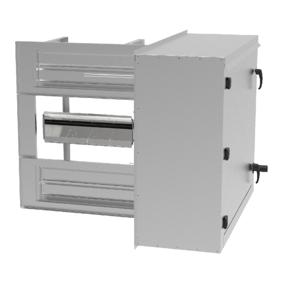
Direct Gas-Fired Heater Modules
ANSI Z83.25 (2017) – CSA 3.19 (2017)
Direct gas-fired process air heaters
DF Series Modules are a Recognized Furnace Component
Design Certified by both Intertek Testing Services (ITS / ETL)
and Underwriters Laboratories (UL)
For Indoor or Outdoor Installation
This Product is intended for installation by Original Equipment Manufacturers
Of Listed Heating Equipment in duct or cabinet mounted applications
on the Negative pressure side of the circulating air blower.
The direct gas-fired heater modules covered by these instructions become a component
of a "Listed" product, subject to the guidelines of application provided in these
instructions and as designated by the Certifying Agency in the Manufacturer's Listing Procedure
Manufactured by:
Heatco Inc
50 Heatco Court
DF-OEM-MAN-LIST-Z83.25-1
Cartersville, Ga. 30120
1
Advertisement
Table of Contents

Summary of Contents for heatco DF Series
- Page 1 Direct Gas-Fired Heater Modules ANSI Z83.25 (2017) – CSA 3.19 (2017) Direct gas-fired process air heaters DF Series Modules are a Recognized Furnace Component Design Certified by both Intertek Testing Services (ITS / ETL) and Underwriters Laboratories (UL) For Indoor or Outdoor Installation...
-
Page 2: Table Of Contents
Report any damage immediately to the transporting agency. After uncrating inspect direct gas-fired heater module for any concealed damage. Table of Contents General Instructions for DF Series Modules. . General Information to include in Installation and Operating Instructions. 3 - 4 4 –... -
Page 3: General Instructions For Df Series Modules
General Instructions for DF Series Direct Gas-Fired Modules This product MUST BE INSTALLED IN A NON-COMBUSTIBLE cabinet. See clearance to combustibles on ratings label. This product is intended to be installed upstream of any cooling coils. A Nameplate / Rating Plate is attached to the direct gas-fired heater module to identify the model and serial number of this product. -
Page 4: Direct-Fired Heat Module Application
Filters must be installed in the return air duct system and have the means to facilitate inspection, maintenance, cleaning, and access to fire protection devices. Filters are required upstream of the direct gas-fired burner assembly. Particulate removal filters are not provided by Heatco and must be approved by the authority having jurisdiction. - Page 5 Minimum distance between the burner and blower should ensure proper stratification of the combustion air. Uniform airflow MUST be directed over the profile plate opening. The direct gas-fired heater module must be installed to fire with, and parallel to, the air flow. The burner performance is dependent on its application and installation in the air handler.
-
Page 6: Paint Booth Application
IV. Paint Booth Application In a paint booth application, an interlock shall be installed in the field to lock out the paint spraying equipment unless the process heater is operated in the ventilation air mode. The customer safety interlock should be wired in series with the heat enable signal. -
Page 7: Cabinet Installation Guidelines
VI. Cabinet Installation Guidelines Verify the following before installing the direct gas-fired heater module: 1. Electrical supply and gas supply match ratings and gas type marked on the direct gas-fired heater module rating plate before installing the module. 2. Direct gas-fired heater module is installed in orientation marked on vestibule. Orientation is specific to airflow direction through the burners of the direct gas-fired heater module. -
Page 8: Circulating Air Supply
Circulating Air Supply VIII. DF Series Direct gas-fired heater modules should ALWAYS be installed with burners in parallel with the circulating airflow direction. The circulating air is to be uniform across the full length of profile plate opening. The direct gas-fired module is designed to operate with all circulating air passing over the burners taken directly from outdoors. -
Page 9: Maximum / Minimum Airflow (Vav)
X. Maximum / Minimum Airflow (VAV) A variable air volume (VAV) option is recommended when a building’s exhaust volume may vary. This option enables the make-up air volume to track the exhaust volume, providing only the required volume of make-up air. A burner bypass damper is required for proper operation of variable volume units. -
Page 10: Gas Supply, Piping And Connections
Figure 7 – Component Locations (Typical) XI. Gas Supply, Piping and Connections 1. Installation and sizing of piping must conform with local building codes and ordinances, or with ANSI Z223.1 the National Fuel Gas Code. In Canada, installation must be in accordance with CAN/CGA –B149.1 Installation Codes. - Page 11 Figure 8 8. A drip leg (sediment trap) and a manual shut off valve must be provided immediately upstream of the gas control on the heating unit. To facilitate servicing of unit, installation of a union is recommended. (See Figure 9) Figure 9 9.
-
Page 12: Direct Gas-Fired Heat Module Controls
XII. Direct Gas-Fired Heat Module Controls Customer Air Control: CA (Customer Provided Modulating Signal): The integral Maxitrol SC11 converts a building controller’s DC output signal of 4-20 mA or 0-10 VDC to a 0-20 VDC signal to control the Maxitrol Selectra modulating valve. See Figure 10A. - Page 13 Each heater is test-fired at the factory and a copy of the Test and Inspection sheet is also included. These documents should be retained by the air handling unit manufacturer for future reference. Heatco Inc. 50 Heatco Court Cartersville, Ga. 30120...


Need help?
Do you have a question about the DF Series and is the answer not in the manual?
Questions and answers